Vortexer apparatus

a technology of vortexer and rotary plate, which is applied in the direction of manufacturing converters, furnaces, charge manipulation, etc., can solve problems such as difficulties, and achieve the effect of facilitating rapid melting of scraps

Active Publication Date: 2006-08-17
THUT BRUNO H
View PDF42 Cites 104 Cited by
  • Summary
  • Abstract
  • Description
  • Claims
  • Application Information

AI Technical Summary

Benefits of technology

[0008] One embodiment of the present invention features a vortexer apparatus that facilitates submergence and melting of metal scrap in molten metal. The vortexer apparatus includes a scrap charge vessel into which the scrap is added to molten metal contained therein, which includes an exterior surface, an interior surface containing molten metal and forming a mouth at an upper end portion, an outlet passageway located near a lower portion of the vessel, and an inlet opening extending between the exterior and interior surfaces of the vessel below the surface of the molten metal contained in the vessel and above the outlet passageway. Molten metal enters the vessel from the inlet opening, in particular, at a location substantially tangential to the interior surface of the vessel. The vessel wall may have a circular, oval or other shape as seen from a top view, and may be vertical, bowl-shaped or conical as seen in a vertical cross-sectional view. Molten metal leaves the vessel through the outlet passageway near the bottom of the vessel. A pump is used for pumping molten metal into the vessel, which includes a shaft driven by a motor at an upper end, an impeller connected to the lower end of the shaft, a base including an impeller chamber in which the impeller is rotatable, an inlet into the impeller chamber of the base and an outlet conduit (e.g., the riser of a transfer pump). Molten metal travels from the impeller chamber to the outlet conduit, which extends from the base to near the inlet opening of the charge vessel. The outlet conduit advantageously can be maintained at a temperature above the temperature at which molten metal solidifies, along the entire length of the outlet conduit. The pump is removable from the pump well for cleaning and repair. All components of the vortexer apparatus that are subjected to the molten metal environment are constructed of refractory material such as graphite or silicon carbide.
[0012] Moreover, the present invention is different from the device described in the U.S. Pat. No. 4,286,985 patent disclosure. That device uses two interconnected inlet passages into the scrap charge vessel, one at the surface of the molten metal and one beneath the level of the molten metal. The present invention does not include a passage at the surface of the molten metal because this disadvantageously exposes more molten metal to the atmosphere and increases oxidation of the metal. In addition, the device of the U.S. Pat. No. 4,286,985 patent disclosure operates based on suction or negative pressure in contrast to the inventive pump which operates more efficiently based on positive pressure. The inventive pump employs a base and optional volute chamber in which the impeller rotates and a removable outlet conduit for directing the molten metal from the impeller chamber to the inlet opening of the charge well. All of these features are lacking in the device of the U.S. Pat. No. 4,286,985 patent disclosure. The device of the U.S. Pat. No. 4,286,985 patent disclosure requires a specially shaped pump well into which an impeller on the end of a shaft is rotated, with an inlet, the first surface passage, the second, below-surface passage, the pump well and the charge well being formed from the same block of material, which complicates the construction, repair and cleaning of that scrap submergence system compared to the present invention.
[0022] Molten metal is drawn into the base inlet by rotation of the impeller in the impeller chamber, leaves the impeller chamber through the base outlet opening and travels through the outlet conduit. Molten metal then travels through the charge well inlet passageway into the charge well. The direction of flow of the molten metal along the charge well inlet passageway and into the interior volume of the charge well, creates a vortex of molten metal inside the charge well. The vortex apparatus operates effectively when the charge well inlet passageway extends generally tangentially to the interior surface of the charge well, as seen in a top view. Reference to tangentially does not require exact alignment of flow between the charge well inlet passageway and the adjacent side wall of the charge well, but connotes circulating molten metal flow along the side walls and separating wall that causes a vortex. The vortex flow of molten metal effectively pulls scrap introduced in the charge well inlet passageway down into the molten metal of the charge well along a vortex flow path and out the charge well outlet passageway. The molten metal and any unmelted scrap travel downwardly through the outlet passageway of the charge well and then to the next destination in the melting process, such as to a dross well or hearth. The hearth is typically an enclosed chamber heated by burners containing most of the volume of molten metal and from which molten metal or solid metal is fed and molten metal is pumped.
[0025] With regard to further variations of the invention, rather than a base outlet passageway that extends from the impeller chamber to an exterior surface of the base and is in fluid communication with a transfer riser that leads to near the charge well inlet passageway, the invention may include a single outlet passageway extending directly from the impeller chamber to near the charge well inlet passageway. This passageway may be in the form of a conduit leading directly from the impeller chamber. Alternatively, the pump base could include a block of material having a passageway formed therein extending from the impeller chamber to near the charge well inlet opening, instead of a riser extending between the base and charge well inlet passageway. In these cases the pump base is separate from the vessel for cleaning and repair. One aspect of the invention includes a discharge passageway extending from the impeller chamber toward an exterior surface of the base, and a conduit in fluid communication with the discharge passageway having one end portion in contact with the base and another end portion in contact with the separating wall and in fluid communication with the charge well inlet passageway. This avoids inefficiencies caused by backflow in the pumping chamber.

Problems solved by technology

It is important to facilitate rapid melting of the scrap, but this is difficult to achieve because the scrap has a low density causing it to float.

Method used


Image

  • Vortexer apparatus
  • Vortexer apparatus
  • Vortexer apparatus

Examples


Embodiment Construction

Vortexer Apparatus with Charge Well Vessel:

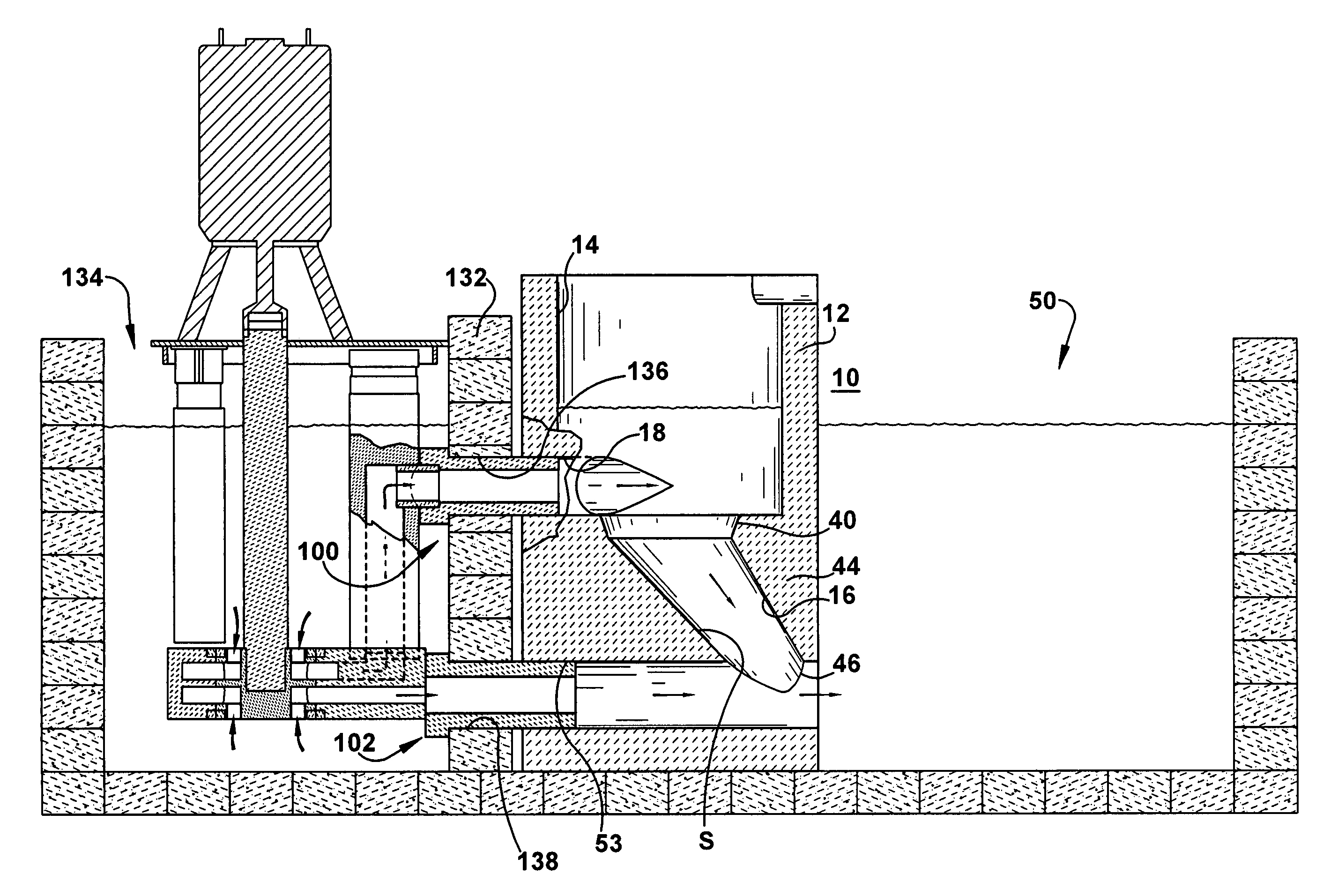
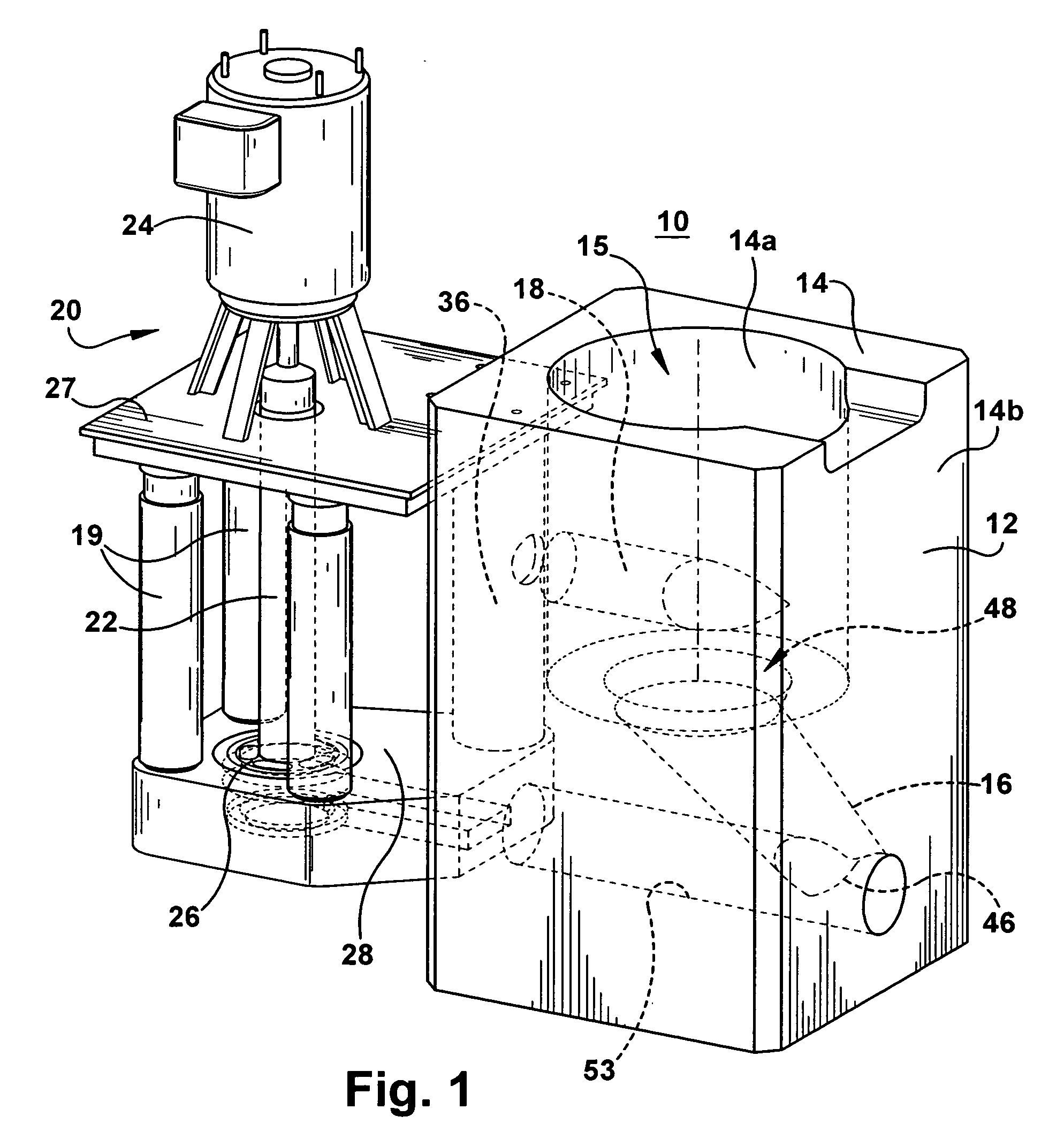
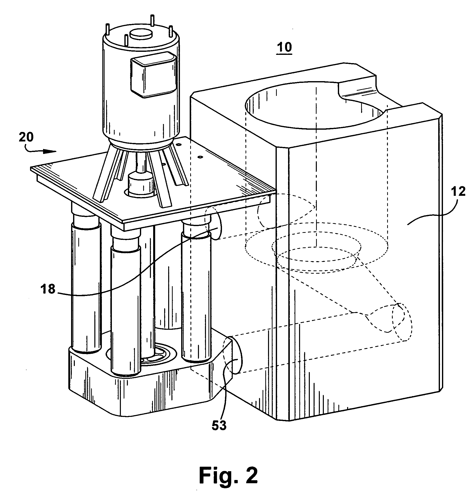
[0047] Referring to the drawings, the vortexer apparatus 10 includes a vortexer or charge vessel 12 formed from a block of refractory material and having a side wall 14, an outlet passageway 16 located near a lower portion of the vessel and an inlet passageway 18 in the side wall of the vessel located below the surface of molten metal contained in the vessel and above the outlet passageway. Molten metal M enters the vessel from the inlet passageway 18 at a location O offset from a central axis CL of the vessel and, in particular, at a location T tangential to the interior surface 14a of the vessel (FIGS. 3, 5 and 6). The vessel inlet passageway 18 can be moved closer to the center line CL if the offset location O is used instead of the tangential location T. The vessel inlet passageway is shown by dotted lines 19 in the position O. The vessel 12 is cylindrical in this exemplary design as seen from a top view. Molten metal leaves the vesse...


PUM

PropertyMeasurementUnit
pressureaaaaaaaaaa
temperatureaaaaaaaaaa
refractoryaaaaaaaaaa

Abstract

The present invention features a vortexer apparatus including a vessel comprising an exterior surface, an interior surface containing fluid and a mouth for receiving material at an upper end portion of the interior surface. In one application the material is metal scrap that is melted in molten metal as the fluid. All components that contact the molten metal are formed of refractory material. An outlet passageway extends downwardly from the interior surface. A vessel inlet opening is located between the exterior and interior surfaces above the outlet passageway. A center line passes through a center of the interior surface and the vessel inlet opening is disposed at a location offset from the center line. A pump is adapted to pump fluid into the vessel effective to form a vortex of fluid in the vessel. The base and impeller are configured and arranged effective to provide molten metal leaving the base outlet with a positive pressure. An outlet conduit extends from the base outlet to near the vessel inlet opening and can be maintained at a temperature above which molten metal solidifies, along its entire length. Instead of the vortexer vessel, the inventive vortexer apparatus may integrate a chamber of a furnace (e.g., a charge well). The chamber may be rectangularor include arcuate portions. Corner inserts may be used to provide the chamber with an oval or generally circular shape that may facilitate the vortex. One feature of the invention is a vortex vessel that includes an offset inlet opening and lower circulation opening. Also featured is a baffle impeller that may be vaned or barrel type. In addition, the invention features a pump having upper and lower impeller chambers separated by a web in the base, and impeller outlets that are isolated from fluid communication with each other.

Description

RELATED APPLICATIONS [0001] This patent application claims benefit of the priority of U.S. provisional patent application Ser. No. 60 / 696,665 filed Jul. 5, 2005, entitled “Pump Having Infinitely Movable Shaft” (Attorney Docket No. 38321); U.S. provisional patent application Ser. No. 60 / 659,356 filed Mar. 7, 2005, entitled “Multi Functional Pump for Pumping Molten Metal” (Attorney Docket No. 37897); U.S. provisional patent application Ser. No. 60 / 672,254 filed Apr. 18, 2005, entitled “Vortexer System with Integrated Charge Well” (Attorney Docket No. 38150); U.S. provisional patent application Ser. No. 60 / 672,813 filed Apr. 19, 2005, entitled “Vortexer System with Integrated Charge Well” (Attorney Docket No. 38151); U.S. provisional patent application Ser. No. 60 / 650,499 filed Feb. 7, 2005, entitled “Vortexer Apparatus” (Attorney Docket No. 37600); and is a continuation-in-part of U.S. Ser. No. 11 / 292,988 filed Dec. 2, 2005, entitled “Gas Mixing and Dispersement in Pumps for Pumping M...

Claims


Application Information

Patent Timeline
Patent Type & Authority Applications(United States)
IPC IPC(8): C21C7/072
CPCC21C1/06F27D3/14F27D27/005Y02P10/20
Inventor THUT, BRUNO H.
Owner THUT BRUNO H
Why Eureka
Try Eureka