Linear electrodynamic system and method

a linear electrodynamic and alternator technology, applied in the direction of dynamo-electric machines, mechanical energy handling, electrical apparatus, etc., can solve the problems of unsatisfactory performance of the electrodynamic system, the amount of mass used for the linear electrodynamic system can be undesirable, and the ease of use of the equipmen

a linear electrodynamic and alternator technology, applied in the direction of dynamo-electric machines, mechanical energy handling, electrical apparatus, etc., can solve the problems of unsatisfactory performance of the electrodynamic system, the amount of mass used for the linear electrodynamic system can be undesirable, and the ease of use of the equipmen

US20060181157A1Inactive Publication Date: 2006-08-17QNERGY

Image

  • Linear electrodynamic system and method
  • Linear electrodynamic system and method
  • Linear electrodynamic system and method

Examples


Embodiment Construction

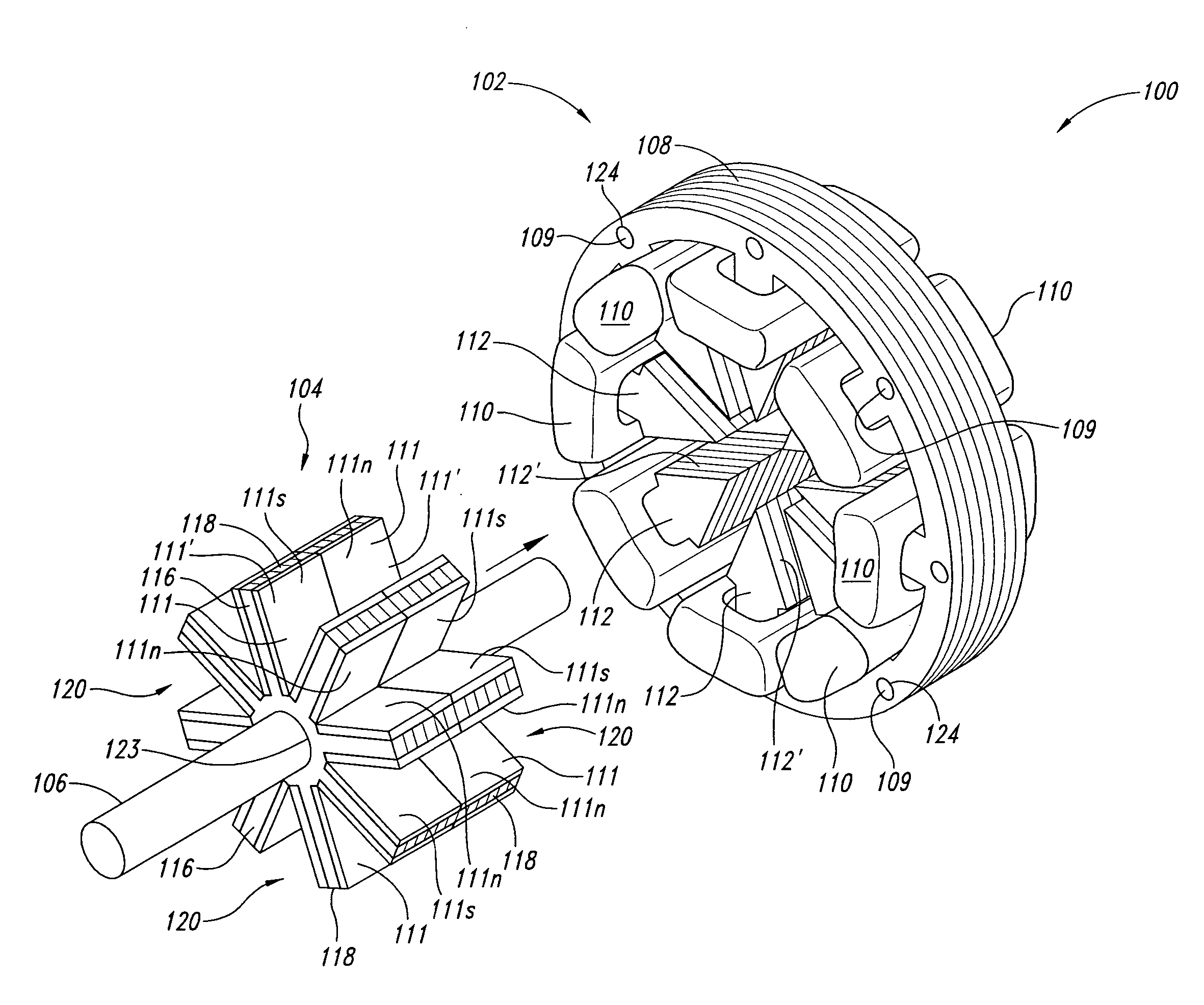
[0021] As will be discussed in greater detail herein, an innovative linear electrodynamic system and method is disclosed to convert linear mechanical motion into an electrical current such as for a linear alternator for heat engines including Stirling cycle engines, or to convert electrical current into linear mechanical motion such as for a linear motor associated with mechanical cooling devices. Due to innovative concepts embodied therein and described below, the innovative linear electrodynamic system has size and weight advantages over conventional linear electrodynamic systems.

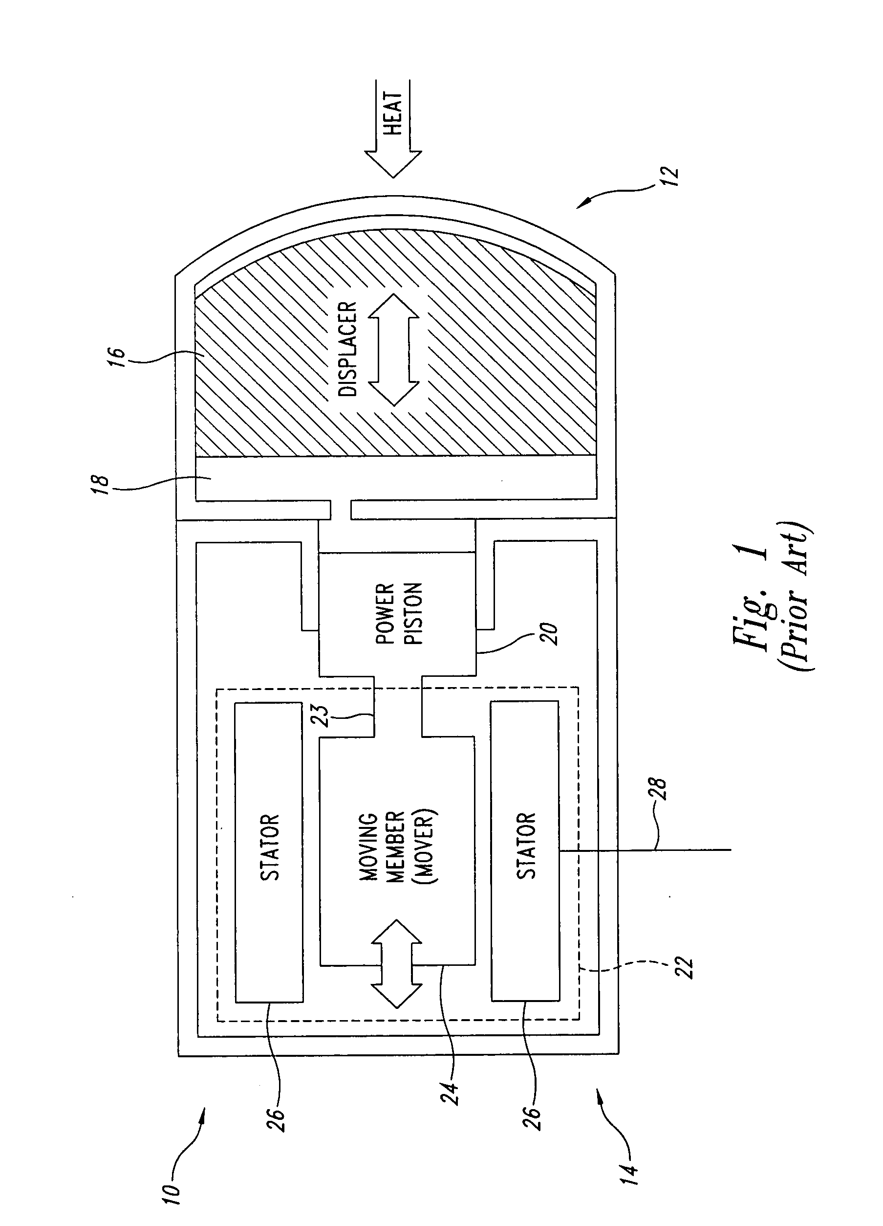
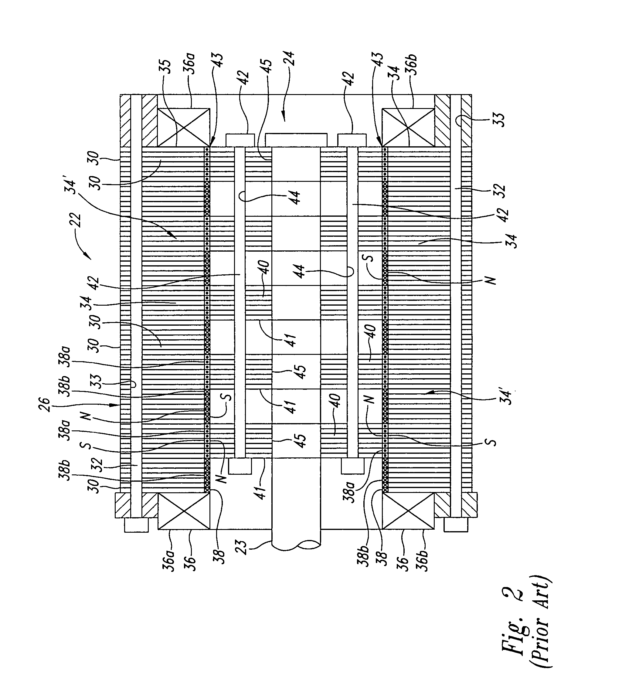
[0022] A conventional electrothermal system 10 using a heat module 12 and a power module 14 is shown in FIG. 1. When in the form of a Stirling cycle engine, the heat module 12 has a displacer 16 and working fluid 18 in fluid communication with a power piston 20, which is part of the power module 14. The power piston 20 of the power module 14 is connected to a conventional linear electrodynamic system 22 ...


PUM


Abstract

An exemplary description provided for patent searches includes a linear electrodynamic system for conversion of mechanical motion into electrical power or conversion of electrical power into mechanical motion involving advantageous use of magnetic material positioned on a mover. Bore surfaces of the magnetic material is shape complementary to bore surfaces of stator poles. Some implementations utilize non-annularly shaped bore surfaces while others utilize annularly shaped bore surfaces.

Description

BACKGROUND OF THE INVENTION [0001] 1. Field of the Invention [0002] The present invention is directed generally to electrodynamic systems and, more particularly, to linear alternators and linear motors. [0003] 2. Description of the Related Art [0004] Linear electrodynamic systems including linear alternators and linear motors are particularly useful, for instance, in combination with Stirling cycle engines for electrical power generation and for refrigeration applications. These electrodynamic systems require substantial mass in their construction for adequate performance. Typically, iron laminations are used for the mover and stator components and copper wire is used for the windings. [0005] Unfortunately, the amount of mass involved with these linear electrodynamic systems can be undesirable, for example, with situations where construction or operational costs are dependent upon equipment weight. As another example, for portable equipment, the amount of mass used for these linear ...

Claims


Application Information

Patent Timeline
17 Aug 2006
Publication
US20060181157A1
IPC
H02K41/00
CPC
H02K7/1884; H02K33/16; H02K35/02
Inventors
QIU, SONGGANG