
Display driver

Inactive Publication Date: 2006-08-17
SEIKO EPSON CORP
View PDF1 Cites 7 Cited by
  • Summary
  • Abstract
  • Description
  • Claims
  • Application Information

AI Technical Summary

Benefits of technology

[0011] An advantage of some aspects of the invention is to enhance the accuracy of inspection and to provide a display driver which can shorten inspection time.
[0013] According to the invention, it is possible to serially output one-pixel display data from the drive voltage output terminal in the test mode inspecting the display driver. As such, when determining an agreement with a test pattern in the test mode, it is possible to determine an agreement between one digital data and another, thereby enabling the accuracy of inspection to be improved and inspection time to be shortened.
[0026] According to the invention, in the test mode inspecting the display data, since the display data to be serially outputted from the hold circuit is inputted through the mode selector into each input terminal of the D / A converter in the same way, a voltage corresponding to each bit of the display data can be outputted from the drive voltage output terminal. By detecting this serially outputted voltage, it is possible to read the data of each bit data of the display data, so that when determining the agreement with a test pattern in the test mode, determination of the agreement between the digital data can be made, thus enabling inspection accuracy to improve and inspection time to shorten.

Problems solved by technology

This hampers reduction of manufacturing cost of the product.
Further, the time required in making the A / D conversion also hampers reduction of the manufacturing cost.
Further, a problem occurs if there are more types of drive voltage.
It becomes difficult to accurately make the A / D conversion of that drive voltage, thus making it impossible to carry out an inspection of high accuracy as well.
Moreover, the inspection referenced above causes another problem which makes it impossible to conduct an inspection of a logic circuit part of a display driver at the time of product inspection.

Method used


Image

  • Display driver
  • Display driver
  • Display driver

Examples


first embodiment

[0046] Display Driver

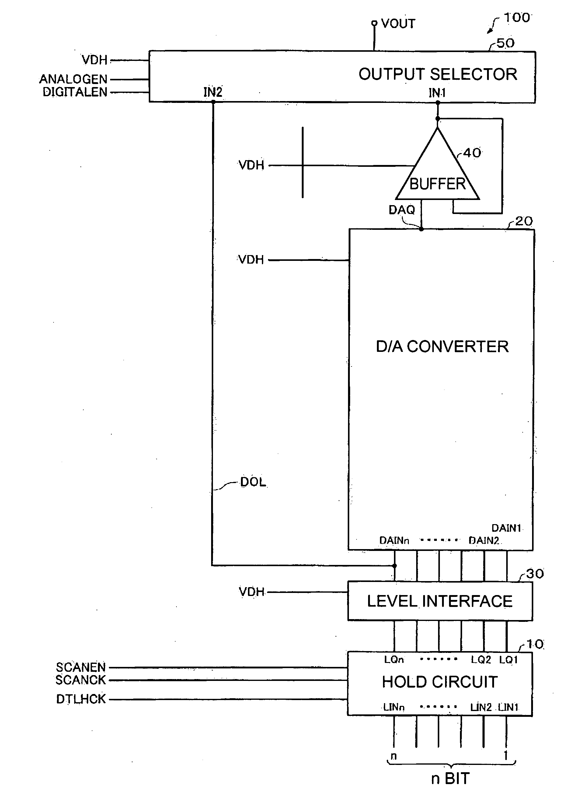
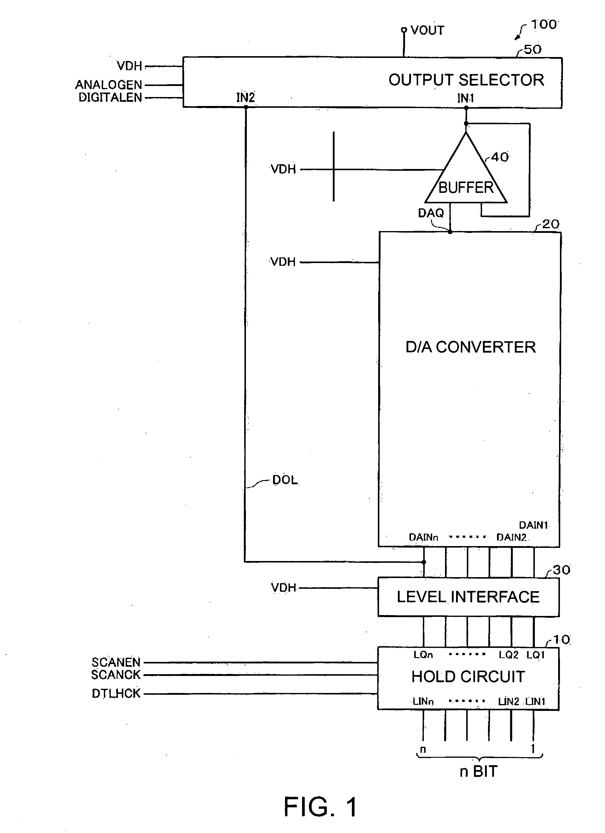
[0047]FIG. 1 is a diagram showing a display driver 100 according to a first embodiment. For the sake of simplifying explanation, the display driver 100 is described for a one-pixel portion, but it is not limited to this. When simultaneously driving a plurality of pixels, it suffices to set up a plurality of display drivers 100.

[0048] The display driver 100 includes, for example, a hold circuit 10 storing display data of a one-pixel portion, a D / A converter 20 converting the display data, a level interface 30 adjusting an output level of the hold circuit 10, a buffer circuit 40 receiving an output of the D / A converter 20 and an output selector 50 outputting a drive voltage. But it is not limited to this. There is no need for the display driver 100 to include all the above-referenced constituent elements. For example, a construction omitting the level interface 30 and the buffer circuit 40 is possible

[0049] The hold circuit 10 includes a plurality of input term...

second embodiment

[0121] Display Driver

[0122]FIG. 7 is a diagram showing a construction example of a display driver 110 according to a second embodiment. The display driver 110 includes a hold circuit 10, a D / A converter 20, a level interface 30, a buffer 40 and a mode selector 60. A major difference between the display driver 110 and the display driver of FIG. 1 is that the display driver 110 includes the mode selector 60.

[0123] Now, the digital output line DOL and the output selector 50 of the display driver 100 in FIG. 1 are not illustrated in the display driver 110 of FIG. 7. However, a construction including these is possible in the display driver 110. Further, the display driver 110 is not limited to the above-referenced construction. For example, a construction omitting the level interface 30 and the buffer 40 will suffice. The hold circuit 10, the D / A converter 20, and the level interface 30 are of the same construction as those illustrated in the display driver 100 of FIG. 1. Moreover, in ...


PUM


Abstract

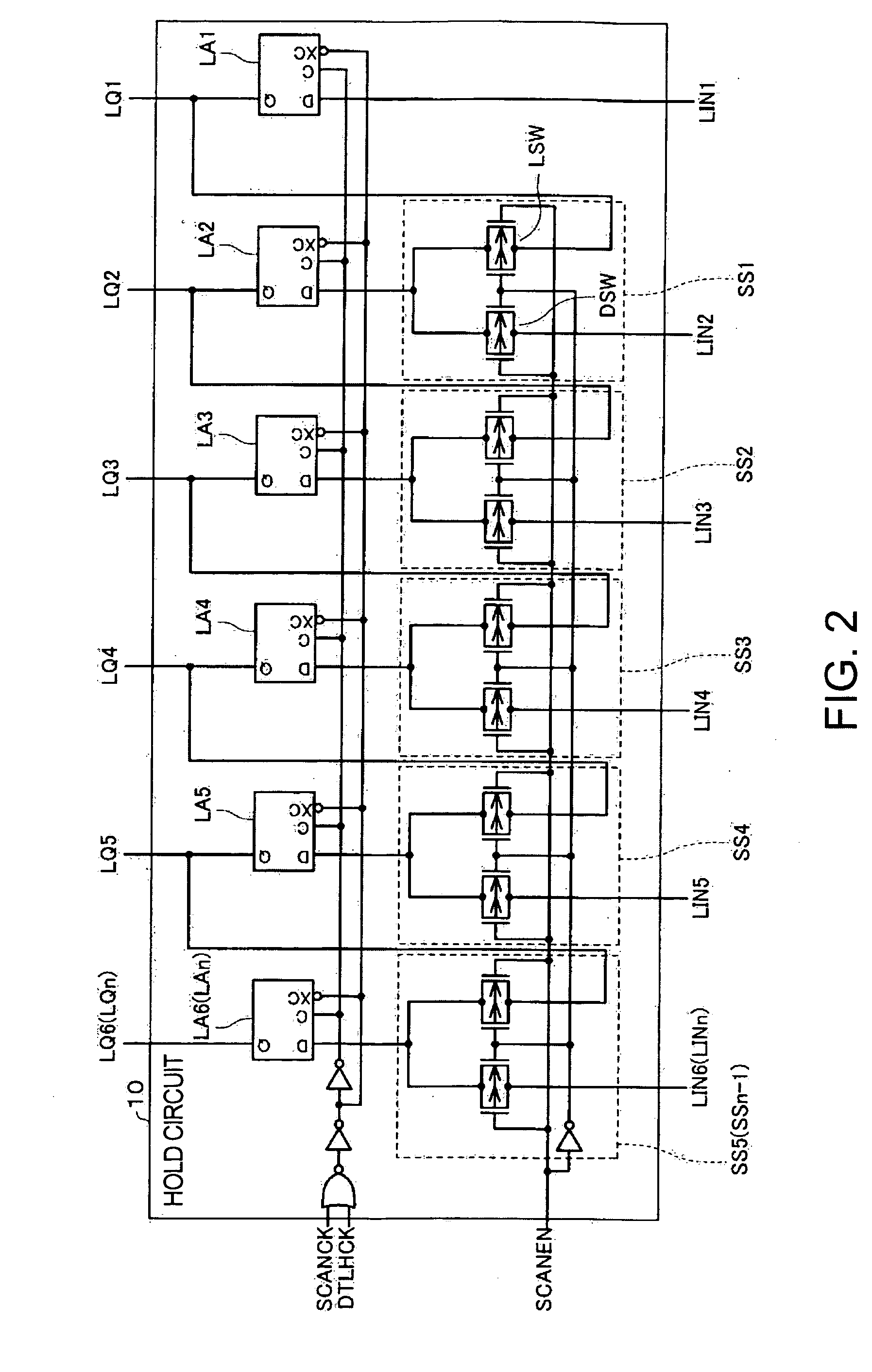
A display driver including: a hold circuit; a D / A converter converting display data from the hold circuit; and an output selector receiving a gray scale voltage based on output of the converter into a first input terminal and outputting a drive voltage to a drive voltage output terminal, the hold circuit including first to n-th latch circuits. In normal operations, the hold circuit outputs data latched in the latch circuits to the converter. In test operations, the hold circuit serially outputs data latched in the latch circuits as serial output data from the n-th latch circuit. The output selector has a second input terminal receiving the serial output data, outputs to the drive voltage output terminal the gray scale voltage inputted into the first input terminal in normal operations, and a voltage based on the serial output data from the hold circuit into the second input terminal in test operations.

Description

RELATED APPLICATIONS [0001] This application claims priority to Japanese-Patent Application No. 2005-038981 filed Feb. 16, 2005 which is hereby expressly incorporated by reference herein in its entirety. BACKGROUND OF THE INVENTION [0002] 1. Technical Field [0003] The invention relates to a display driver. [0004] 2. Related Art [0005] An inspection such as confirmation of operations for shipping a product is typically conducted for a display driver for driving a display panel. For example, when inspecting a display driver for driving a TFT panel, as an inspection item, a drive voltage outputted from the display driver is inspected. In this case, since the drive voltage outputted from the display driver of a product is analog, its drive voltage is subjected to one A / D conversion, and the inspection is conducted based on converted digital data. [0006] On the other hand, display drivers meeting demands of displaying high resolution and high gray scale are beginning to be widely used. F...

Claims


Application Information

Patent Timeline
IPC IPC(8): G09G5/00
CPCG09G3/006G09G2300/08G09G2310/027G09G2310/08
Inventor OTA, YUSUKE
Owner SEIKO EPSON CORP
Learn More