Tolerance ring with debris-reducing profile

a technology of tolerance rings and debris, applied in the field of tolerance rings, can solve problems such as data loss, disk and head tribological failure, and interface tribological failur

Inactive Publication Date: 2006-08-17
INTRL PLEX TECH INC
View PDF11 Cites 42 Cited by
  • Summary
  • Abstract
  • Description
  • Claims
  • Application Information

AI Technical Summary

Problems solved by technology

However, because there is relative motion between the disk surface and the head due to the disk rotation and head actuation, continuous contact between the head and disk can lead to tribological failure of the interface.
Such tribological failure, known colloquially as a “head crash,” can damage the disk and head, and usually causes data loss.
In addition to tribological consequences, contamination and debris at or near the head disk interface can force the head away from the disk.
The resulting temporary increases in head-disk spacing cause magnetic read / write errors.
For example, the actuator arm cannot be designed to be too massive because it must accelerate very quickly to reach information tracks containing desired information.
Otherwise, the time to access desired information may be unacceptable to the user.
The present inventors recognized that the forceful insertion of the actuator pivot bearing cartridge into a generally cylindrical hole in the actuator arm body, with interference that radially preloading the tolerance ring, can cause the tolerance ring to shear metal fragments from either the actuator pivot bearing sleeve flange or the actuator arm body (whichever component is not the one to which the tolerance ring is first installed), and such fragments can later contaminate the head-disk interface and ultimately lead to a head crash and possibly to data loss.
However, even when a conventional tolerance ring is installed first into the actuator arm, the stainless steel surface of the actuator pivot bearing may be scraped when it is pushed into the interior of the installed tolerance ring.
Consequently, the installation of a conventional tolerance ring is still prone to generate debris.
The industry's marked reliance on pre- and post-assembly cleaning steps survives even though such steps are not thorough in their removal of contaminants and debris.
Assembly in clean environments also does not prevent the generation of contaminates and debris during assembly operations performed within those clean environments.
Still, such consideration is often restricted to the selection of lubricants and adhesives.

Method used


Image

  • Tolerance ring with debris-reducing profile
  • Tolerance ring with debris-reducing profile
  • Tolerance ring with debris-reducing profile

Examples


Embodiment Construction

[0036] A tolerance ring for applications requiring cleanliness has contacting portions having a novel profile that reduces debris generation during installation of the tolerance ring while still providing adequate stiffness after installation.

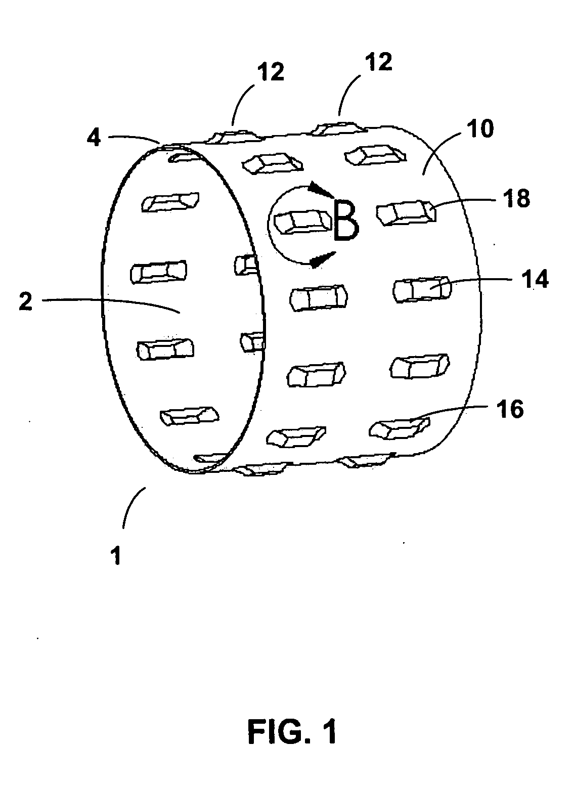
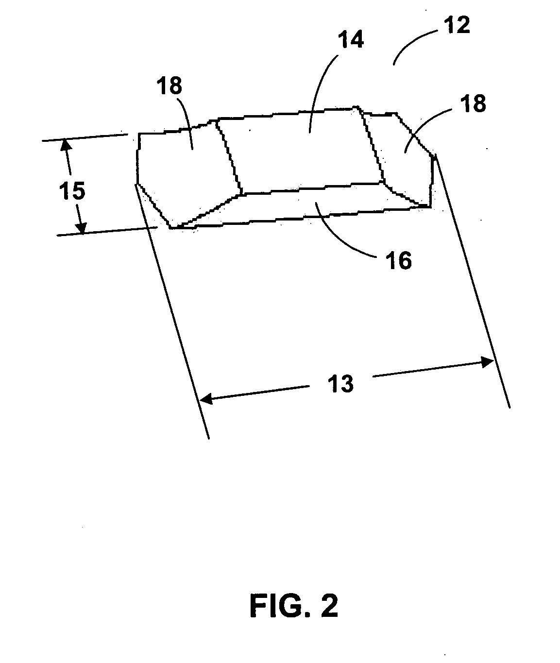
[0037]FIG. 1 shows a perspective view of a tolerance ring according to an embodiment of the present invention. The tolerance ring 1 has a cylindrical base portion 10 and a plurality of contacting portions 12. Elastic radial expansion and contraction of cylindrical opening 2 is facilitated by an axially-oriented gap 4 in the circumference of tolerance ring 1. The contacting portions 12 have central regions 14, circumferential transition regions 16, and axial transition regions 18.

[0038]FIG. 2, which is an expanded view of the single contacting portion 12 within detail region B of the previous figure, depicts the foregoing regions with greater clarity. Contacting portion 12 has overall axial length 13 and overall circumferential width 15. Note ...


PUM

PropertyMeasurementUnit
circumferential transition lengthaaaaaaaaaa
axial transition lengthaaaaaaaaaa
radius of curvatureaaaaaaaaaa

Abstract

A tolerance ring for applications requiring cleanliness has contacting portions having a novel profile that reduces debris generation during installation of the tolerance ring while still providing adequate stiffness after installation. The tolerance ring is suitable for cylindrical interface applications where both a reduction in debris generation and high interface stiffness are desirable, such as the interface between an actuator pivot bearing and an actuator arm in a magnetic hard disk drive.

Description

BACKGROUND OF THE INVENTION [0001] 1. Field of the Invention [0002] This invention relates generally to tolerance rings designed for use in clean environments and particularly to tolerance rings for use in information storage devices. [0003] 2. Description of Related Art [0004] In hard disk drives, magnetic heads read and write data on the surfaces of co-rotating disks that are co-axially mounted on a spindle motor. The magnetically-written “bits” of written information are therefore laid out in concentric circular “tracks” on the surfaces of the disks. The disks must rotate quickly so that the computer user does not have to wait long for a desired bit of information on the disk surface to translate to a position under the head. In modern disk drives, data bits and tracks must be extremely narrow and closely spaced to achieve a high density of information per unit area of the disk surface. [0005] The required small size and close spacing of information bits on the disk surface have ...

Claims


Application Information

Patent Timeline
Patent Type & Authority Applications(United States)
IPC IPC(8): G11B5/48
CPCF16C27/00G11B5/4813F16C2370/12F16D1/0835
Inventor HANRAHAN, KEVIN P.DEXTER, DAVID D.SCHMIDT, RYAN J.SPRANKLE, MATTHEW S.
Owner INTRL PLEX TECH INC
Why Eureka
Try Eureka