Video compression and decompression system with postfilter to filter coding artifacts

a video compression and decompression system technology, applied in the field of video compression and decompression systems, can solve the problems of inability to detect the boundaries between moving objects and stationary background that fall within these blocks, the size of the quantization steps needs to be relatively large, and the visual quality of the decoded sequence that may be displayed

Inactive Publication Date: 2006-08-17
LILLEVOLD KARL
View PDF16 Cites 13 Cited by
  • Summary
  • Abstract
  • Description
  • Claims
  • Application Information

AI Technical Summary

Problems solved by technology

If the available transmission bandwidth is relatively small, with respect to the complexity of the image to be transmitted, the size of the quantization steps needs to be relatively large.
In that case, the resulting coarse quantization of the DCT coefficients introduces coding artifacts into the transmitted image and severely degrades the visual quality of the decoded sequence that may be displayed.
The majority of the energy contained in the prediction error signal is the result of a motion estimator's inability to distinguish between differently moving objects within the video sequence.
Since the motion estimator tries to match blocks of pixels between temporarily adjacent frames, the boundaries between moving objects and stationary background that fall within these blocks cannot be detected.
If these prediction errors are coarsely quantized, impulsive artifacts result that change over time and tend to swarm around the moving object, similar to a mosquito.
These artifacts are due to the combination of quantization and dividing the prediction error signal into blocks.
Furthermore, since each block is quantized separately, the errors are most visible at the block boundaries.
However, such an estimation of the noise power based on the quantization step size is not a reliable indicator as to the spatial location of mosquito artifacts and blocking artifacts within the decompressed video.
For example, oversmoothing or blurring of the decompressed video occurs due to inaccurate estimates of the compressed video's signal-to-noise ratio.

Method used


Image

  • Video compression and decompression system with postfilter to filter coding artifacts
  • Video compression and decompression system with postfilter to filter coding artifacts
  • Video compression and decompression system with postfilter to filter coding artifacts

Examples


Embodiment Construction

[0022] In the following description, reference is made to the accompanying drawings, which form a part hereof, and which show, by way of illustration, specific embodiments in which the invention may be practiced. It is to be understood that other embodiments may be utilized and structural changes may be made without departing from the scope of the present invention. Where possible, the same reference numbers will be used throughout the drawings to refer to the same or like components. Numerous specific details are set forth in order to provide a thorough understanding of the present invention. However, it will be obvious to one skilled in the art that the present invention may be practiced without the specific details or with certain alternative equivalent devices and methods to those described herein. In other instances, well-known methods, procedures, components, and devices have not been described in detail so as not to unnecessarily obscure aspects of the present invention.

[002...


PUM


Abstract

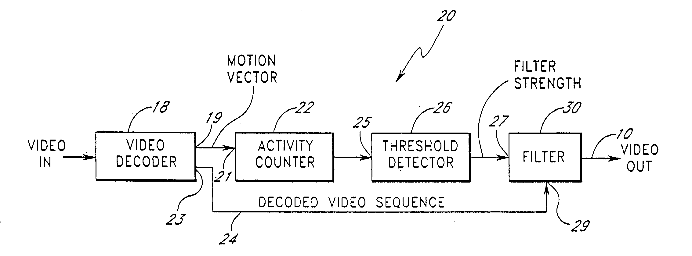
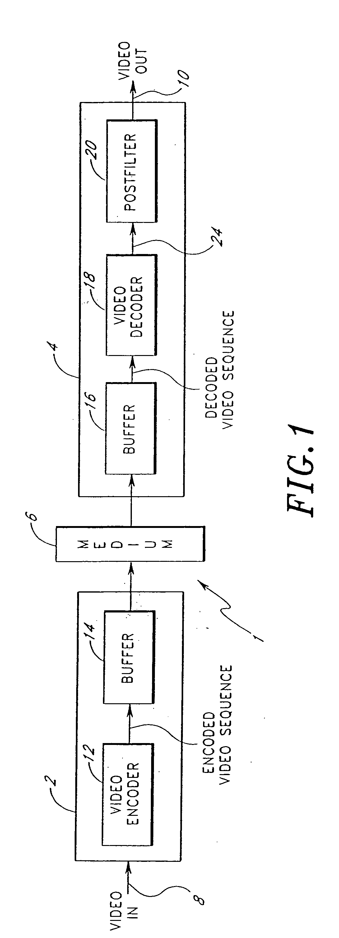
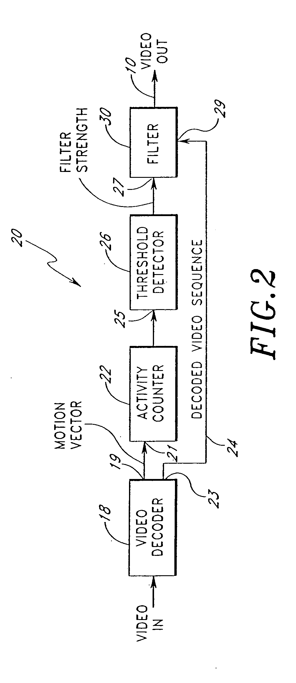
A video compression and decompression system has an input to receive an encoded video sequence and an output for a decoded video sequence. A video decoder is coupled to the input and decode the received encoded video sequence. A filter module is coupled to the video decoder and the output and filters the decoded video sequence from the video decoder. The filter module has a variable filter strength that is a function of detected motion activity within the video sequence. The filter module filters coding artifacts, such as mosquito artifacts and blocking artifacts from the decoded video sequence so that the displayed video is more pleasing for a viewer's eyes.

Description

RELATED APPLICATIONS [0001] This application is incorporated by reference and is a continuation of U.S. patent application Ser. No. 09 / 731,474, filed Dec. 6, 2000.BACKGROUND OF THE INVENTION [0002] 1. Field of the Invention [0003] The invention pertains to the field of video compression and decompression systems. More particularly, the invention pertains to a system and method for reducing compression artifacts in a video compression and decompression system. [0004] 2. Description of the Related Art [0005] Systems for applications of video and visual communications transmit, process and store large quantities of video data. To create a video presentation, such as a video movie, a rendering video system displays the video data as a sequence of individual digital images, also referred to as “frames,” thereby simulating movement. In order to achieve a video presentation with an acceptable video quality, or to enable transmission and storage at all, the video systems process and modify ...

Claims


Application Information

Patent Timeline
Patent Type & Authority Applications(United States)
IPC IPC(8): G06K9/36H04N11/02
CPCH04N19/139H04N19/172H04N19/46H04N19/86H04N19/117H04N19/179H04N19/44H04N19/61
Inventor LILLEVOLD, KARL
Owner LILLEVOLD KARL
Why Eureka
Try Eureka