Multistage sealed coolant pump

a technology of centrifugal pump and sealed seal, which is applied in the direction of pump, positive displacement liquid engine, machine/engine, etc., can solve the problems of known single impeller pump efficiency that is lower, and achieve the effect of reducing motor current, reducing pumping pressure, and prolonging li

Inactive Publication Date: 2006-08-17
MCCARTHY JAMES
View PDF27 Cites 3 Cited by
  • Summary
  • Abstract
  • Description
  • Claims
  • Application Information

AI Technical Summary

Benefits of technology

[0005] In accordance with the present invention, a multistage sealed pump is provided for use in an X-ray tube cooling system which is substantially more efficient than pumps of known construction and which provides substantially higher pumping pressure at lower motor current and longer life. The pump employs multiple impellers which are plumbed in series and which are directly coupled to an electrical motor which with the impellers is submerged and runs in the coolant liquid. The impellers and motor are sealed within a housing and the pump unit is hermetically sealed, with no rotatable shaft seals being used or required. The multiple stages of the pump yield higher hydraulic efficiency than a single stage pump with the same performance. In addition, higher power motors can be employed in a smaller physical space since the motor windings are more effectively cooled while submerged in the coolant liquid, in contrast to a motor running in air.
[0006] In one embodiment, the multistage pump employs a motor having oppositely extending motor shaft ends, with one or more impellers on each end of the motor shaft. This embodiment has the advantage of balancing the thrust of the impellers and thereby reducing the load on the motor bearings, with consequent increased pump life. The cooling liquid can be transferred from stage to stage by various fluid paths. In one aspect of the invention, coolant is conveyed from stage to stage by interconnecting tubing external of the housing. In another aspect of the invention, coolant is conveyed between stages through a hollow motor shaft. In yet another aspect, coolant is transported through tubing within the pump housing. In a further aspect, the coolant is conveyed between stages through the motor casing. In another embodiment, the multiple impellers can be directly mounted on a shaft extending from a single end of the motor.

Problems solved by technology

As a consequence, known single impeller pumps have lower efficiency.

Method used


Image

  • Multistage sealed coolant pump
  • Multistage sealed coolant pump
  • Multistage sealed coolant pump

Examples


Embodiment Construction

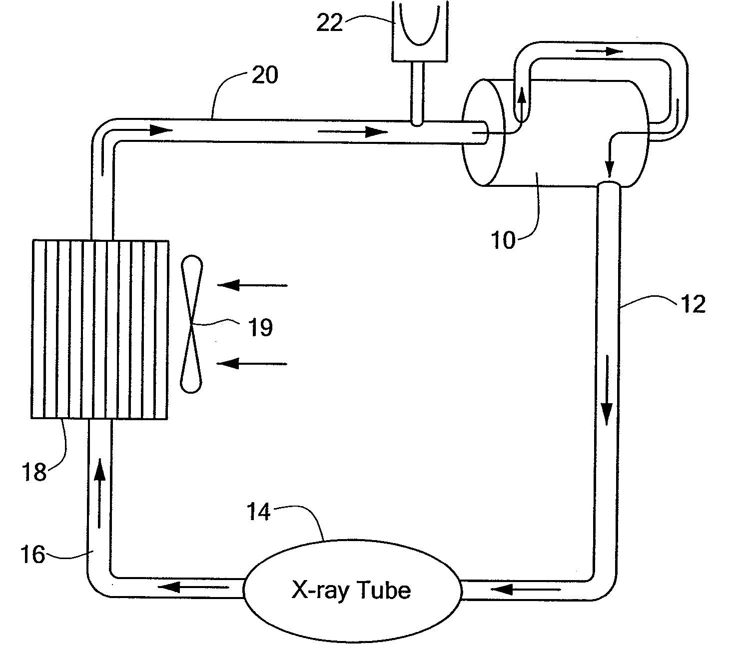
[0019] An X-ray tube cooling system having a pump in accordance with the invention is shown diagrammatically in FIG. 1. A pump 10 constructed according to the invention and to be further described below, has its output coupled via tubing 12 to a housing 14 of an X-ray tube, and via tubing 16 to a heat exchanger 18, and thence via tubing 20 to the input of pump 10. The system contains a coolant liquid which typically is an oil such as Shell Diala. An expansion tank 22 is provided for accommodating expansion of the coolant as it is heated during use of the X-ray tube. Flow rates of about 8 gallons per minute or higher are typical for coolant flow in a CT system in which the X-ray tube is employed.

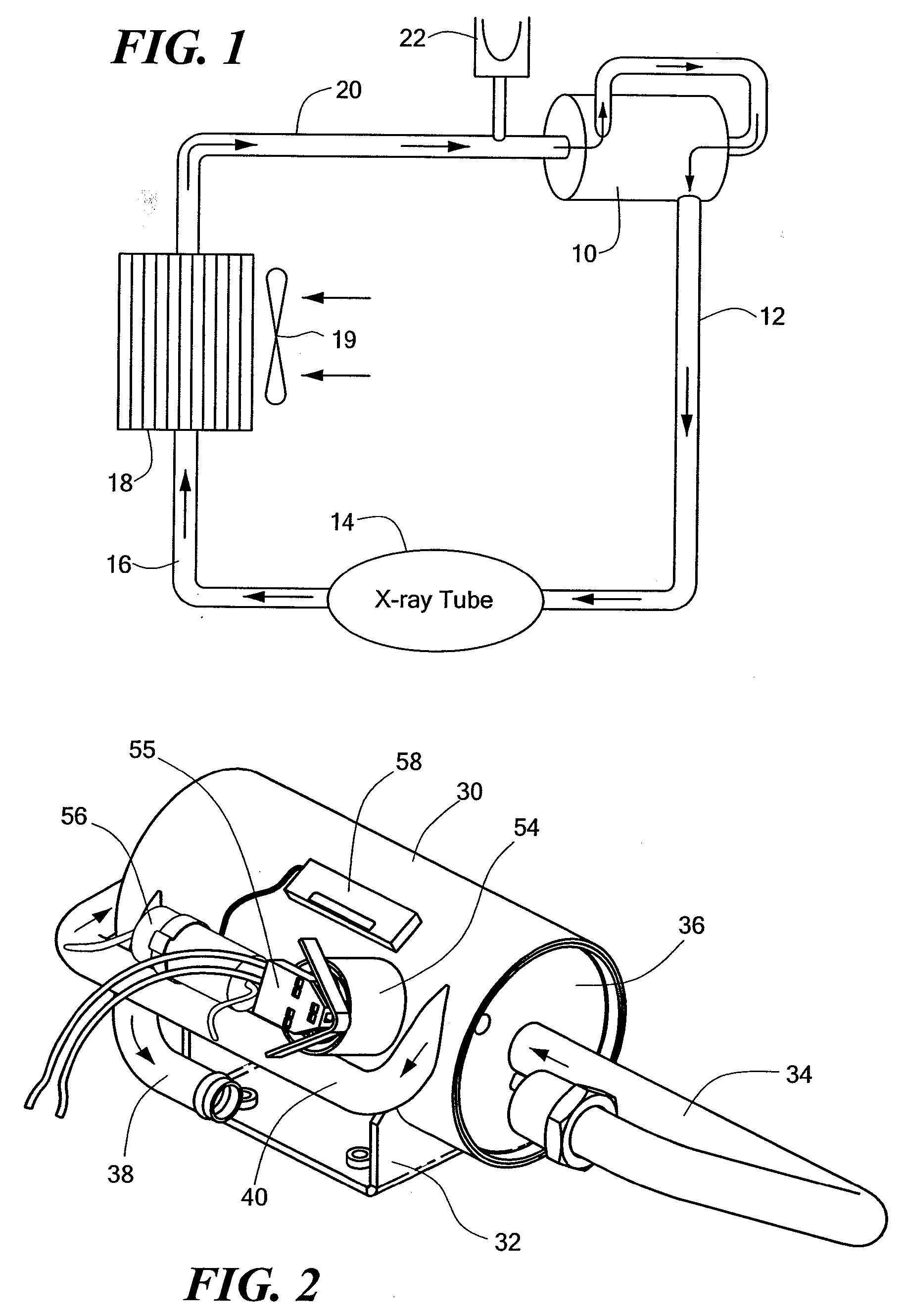
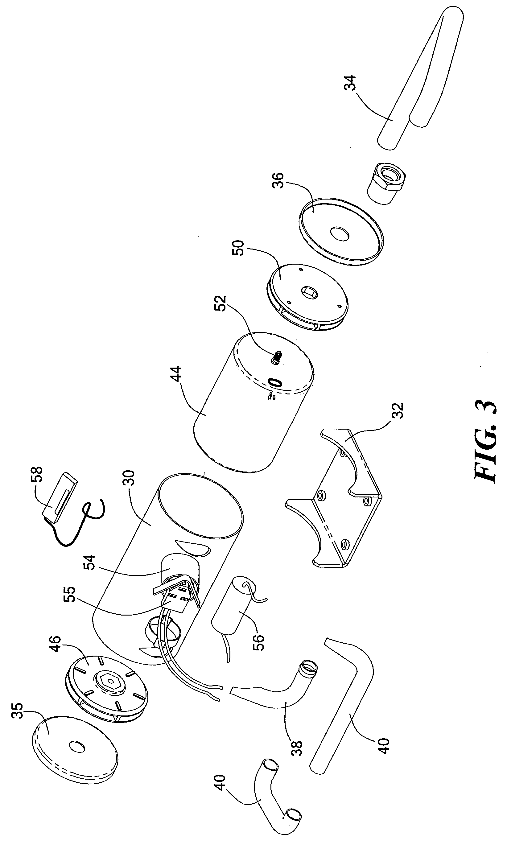
[0020] The pump is shown in a preferred embodiment in FIGS. 2-4 and comprises a cylindrical housing 30 attached to a base or mounting bracket 32 for attaching the housing 30 to a mounting surface. An inlet tube 34 is connected at one end to one end cap 36 of the housing and is welded or othe...


PUM


Abstract

A multistage sealed pump is provided for use in an X-ray tube cooling system which is substantially more efficient than pumps of known construction and which provides substantially higher pumping pressure at lower motor current than conventionally. Cooling liquid can be transferred from stage to stage by interconnecting tubing external of the housing or within the housing, through a hollow motor shaft, or through the motor casing. In another embodiment, the multiple impellers can be directly mounted on a shaft extending from a single end of the motor.

Description

CROSS REFERENCE TO RELATED APPLICATIONS [0001] This application claims priority of U.S. patent application Ser. No. 10 / 413,062, filed Apr. 13, 2003, which is a non-provisional application of U.S. Provisional Patent Application No. 60 / 372,964 entitled MULTISTAGE HERMETICALLY SEALED, DIRECT DRIVE CENTRIFUGAL PUMP, filed on Apr. 16, 2002 the disclosure of both of which are incorporated by reference herein and made a part hereof.BACKGROUND OF THE INVENTION [0002] This invention relates to coolant pumps and more particularly, to a multistage sealed direct drive centrifugal pump which is especially useful in X-ray tube cooling systems. [0003] For the cooling of an X-ray tube such as used in a CT system, a coolant liquid is circulated around the X-ray tube to cool the tube during use. A pump is employed to circulate the coolant in a cooling system and X-ray system specifications require that the pump have stringent characteristics to be properly employed in the X-ray system. More particula...

Claims


Application Information

Patent Timeline
Patent Type & Authority Applications(United States)
IPC IPC(8): F04B39/06
CPCF04D1/063F04D13/0606
Inventor MCCARTHY, JAMES
Owner MCCARTHY JAMES
Why Eureka
Try Eureka