Carriage slide valve and transfer pump and pump truck with same

A technology for conveying pumps and carriages, which is applied in the direction of sliding valves, parts of pumping devices for elastic fluids, valve devices, etc., and can solve the problems of reduced reliability and service life, sealing performance affecting discharge pressure, and sliding rod sealing Reduced coaxiality and other problems to achieve the effect of improved reliability, reliable sealing and high coaxiality

Active Publication Date: 2018-07-20
山东瀚纶环保机械有限公司
View PDF8 Cites 0 Cited by
  • Summary
  • Abstract
  • Description
  • Claims
  • Application Information

AI Technical Summary

Problems solved by technology

This Chinese patent application solves the above problems, but after long-term use, the concentricity between the slide rod and its seal will gradually decrease due to wear and tear, which will lead to reduced sealing performance and even damage to the seal, affecting the sealing effect
[0004] On the other hand, the delivery pump using this slide valve will not only affect the discharge pressure due to the reduction of sealing performance, but also reduce its reliability and service life due to the wear of the slide rod seal.

Method used


Image

  • Carriage slide valve and transfer pump and pump truck with same
  • Carriage slide valve and transfer pump and pump truck with same
  • Carriage slide valve and transfer pump and pump truck with same

Examples


Embodiment 1

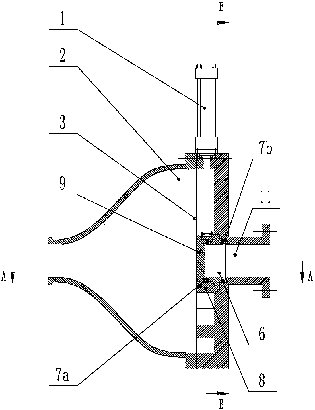
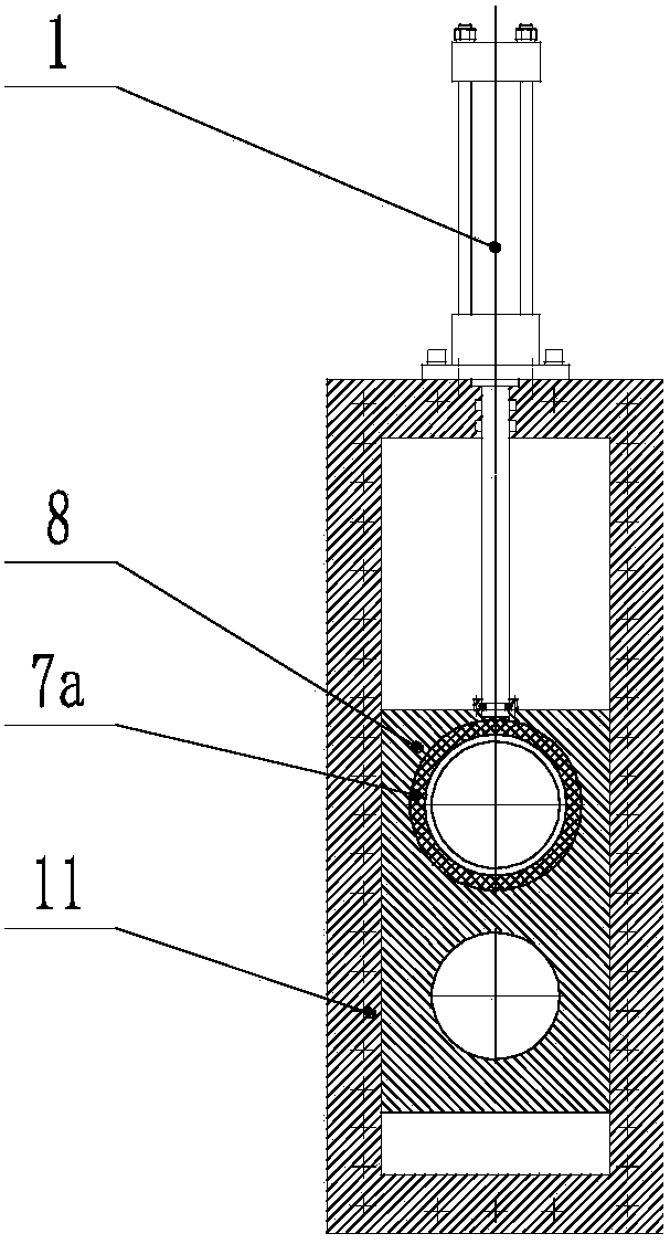
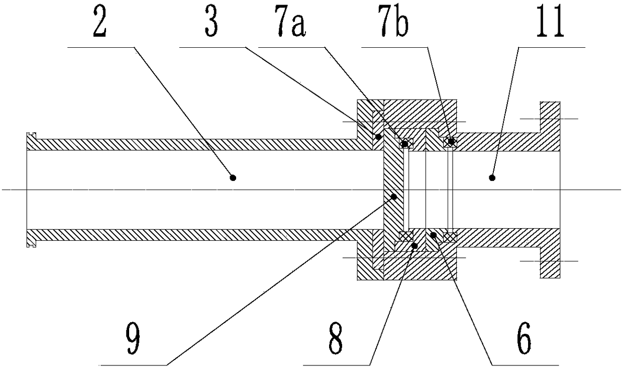
[0085] see figure 1 , figure 2 and image 3 , which shows a schematic diagram of a carriage slide valve according to a preferred embodiment of the present invention. The slide valve shown in the figure includes: a driving device 1, an auxiliary valve body 2, a sliding pressure plate 3, a through-hole body 6, a first elastic body 7a, a second elastic body 7b, a drag body 8, a valve plate 9, a main valve Body 11.

[0086] Wherein, there is a feed hole on the main valve body 11, and the material can pass through the feed hole of the main valve body 11; the through hole body 6 is provided with a through hole; the drag body 8 is provided with a mounting hole; the first elastic The body 7a and the second elastic body 7b are elastic seals with sealing function, which can be rubber seal rings, polyurethane seal rings or polytetrafluoroethylene seal rings, etc.; the driving device 1 is a hydraulic cylinder or an air cylinder.

[0087] The auxiliary valve body 2 and the main valve ...

Embodiment 2

[0093] see Figure 4 , Figure 5 and Figure 6 , which shows a schematic diagram of another preferred embodiment of the carriage slide valve of the present invention, the carriage slide valve includes: a driving device 1, an auxiliary valve body 2, a guide plate 4, a slide rod 5, a through-hole body 6, a first Elastic body 7a, second elastic body 7b, driving body 8, valve plate 9, main valve body 11.

[0094]Wherein, the main valve body 11 is provided with a feed hole, the drag body 8 is provided with an installation hole, the through hole body 6 is provided with a through hole, and the guide plate 4 is provided with a guide hole; the auxiliary valve body 2 and the main valve body 11 Installed together, the driving device 1 is connected with the main valve body 11, and the power output end of the driving device 1 is connected with two slide rods 5, and the two slide rods 5 are respectively installed in the guide holes of the two guide plates 4, and the guide plates 4 is loc...

Embodiment 3

[0100] see Figure 7 , Figure 8 , Figure 9 and Figure 10 , which shows a schematic diagram of another preferred embodiment of the carriage slide valve of the present invention, the carriage slide valve includes: a driving device 1, an auxiliary valve body 2, a sliding pressure plate 3, a guide plate 4, a slide rod 5, a through-hole body 6. Elastic body 7, drag body 8, valve plate 9, material passing plate 10, main valve body 11, main valve body 11 and auxiliary valve body 2 are connected.

[0101] The slide valve of this embodiment has two gate valve units, and the main valve body 11 has two material passing holes, and the two material passing holes belong to the two gate valve units, and each gate valve unit includes a driving device 1, Two sliding pressure plates 3, two guide plates 4, two sliding rods 5, a through hole body 6, an elastic body 7, a drag body 8, a valve plate 9 and a material passing plate 10.

[0102] The auxiliary valve body 2 is connected with the m...


PUM


Abstract

Provided is a carriage spool valve comprising: a main valve body (11) with a charging hole being provided therein; an auxiliary valve body (2) which is directly or indirectly coupled with the main valve body (11); a driving device (1) having a power output end; a dragged body (8) which is located between the main valve body (11) and the auxiliary valve body (2), a mounting hole being provided in the dragged body (8); a valve plate (9) which is mounted in the mounting hole of the dragged body (8) in an axially movable manner and blocks the mounting hole; and a through-hole body (6) which is mounted in the dragged body (8) and / or in a mounting hole of the main valve body (11) in an axially movable manner. A through-hole and an elastomer (7) are provided on the through-hole body (6), the elastomer being mounted in the mounting hole of the main valve body (11) and / or in the charging hole of the main valve body (11). The dragged body (8) is directly or indirectly connected to the power output end of the driving device (1) and can be driven by the driving device (1) to perform a reciprocating motion so as to open or close the charging hole in the main valve body (11). In addition, a delivery pump having the carriage spool valve is also disclosed.

Description

technical field [0001] The invention relates to the field of pipeline conveying equipment, in particular to a carriage slide valve used for pipeline conveying materials such as slurry and paste, and a conveying pump and a pump truck equipped with the same. Background technique [0002] In the pipeline transportation project of mud, concrete, coal slime, municipal sludge, printing and dyeing sludge, chemical sludge, liquid food raw materials and other materials, it is necessary to control the on-off and reversing of the conveying pipeline. The existing technology mainly uses liquid reversing Valves, but because these materials contain a large amount of solid components, and these solid components can easily enter the gap between the moving parts of the valve under high pressure, and even form accumulations, thus blocking the valve. [0003] In order to solve this problem, the inventor of this patent has developed a new type of valve, see Chinese Patent Application No. 2015108...

Claims


Application Information

Patent Timeline
Patent Type & Authority Patents(China)
IPC IPC(8): F16K3/02F15B15/18F04B53/10E04G21/04
CPCF16K3/02
Inventor 巩高铄高红杰
Owner 山东瀚纶环保机械有限公司
Why Eureka
Try Eureka