Hydraulic pump control system of hydraulic working machine

a technology of hydraulic working machines and control systems, which is applied in the direction of servomotors, constructions, servomotor circuits, etc., can solve the problems of increasing cost, affecting the efficiency of hydraulic actuators, and unable to control the flow rate of pumps and hydraulic actuators, so as to reduce the bleed-off flow rate and the discharge flow rate, cost suppression, and energy saving

Active Publication Date: 2018-08-23
CATEPILLAR SARL
View PDF8 Cites 1 Cited by
  • Summary
  • Abstract
  • Description
  • Claims
  • Application Information

AI Technical Summary

Benefits of technology

[0014]According to the first aspect of the invention, it is possible to reduce the bleed-off flow rate and the discharge flow rate of the hydraulic pump which can contribute to energy saving. Moreover, it is possible to operate the hydraulic actuator equally with the conventional open center control system even in a virtual bleed-off control mode. Furthermore, in the state in which the bypass cut valve and the negative control pressure output valve are not operated, the negative control pressure generated by the negative control throttle is guided to the variable displacement means of the hydraulic pump. Thus, even when the bypass cut valve or the negative control pressure output valve break down, it is possible to perform pump flow rate control of the hydraulic pump using the negative control pressure generated by the negative control throttle. In addition, the change from the existing open center control system is also easy, which can significantly contribute to cost suppression.
[0015]According to the third aspect of the invention, it is possible to more reliably set the operation of the hydraulic actuator in the virtual bleed-off control to be equivalent to conventional open center control.
[0016]According to the fourth aspect of the invention, it is possible to suppress the frequency variation of the calculated bleed-off reduction flow rate, in order to prevent hunting of the pump pressure.
[0017]According to the fifth aspect of the invention, the damping coefficient of the hydraulic system increases, which can contribute to the suppression of hunting.
[0018]According to the sixth aspect of the invention, since pump pressure rises smoothly, operability is improved, and when the hydraulic actuator manipulation tool is operated in stages or when a reversing operation of suddenly switching the hydraulic actuator manipulation tool in the opposite direction is performed, it is possible to avoid the problem that the discharge oil of the hydraulic pump is confined and the pump pressure rapidly rises.
[0019]According to the seventh aspect of the invention, it is possible to reduce the hysteresis of the negative control pressure output valve and to improve the responsiveness and controllability.

Problems solved by technology

However, in the open center control system configured to control the pump flow rate by the negative control pressure using the open center type flow rate control valve, there was a problem in that energy saving was impeded by the large bleed-off flow rate flowing from the center bypass oil passage to the oil tank.
Therefore, when there is a failure of a pressure sensor configured to detect the pump discharge pressure or the electromagnetic proportional valve, there is a problem that it is not possible to control the pump flow rate and operate the hydraulic actuator.
If an existing system using the conventional open center type flow rate control valve is changed to the published control system in order to reduce the bleed-off flow rate, there is a problem of increase in cost since special flow rate control valves at least equal in number to the hydraulic actuators need to be prepared.
Thus, it is expected that the bleed-off flow rate decreases and damping of the hydraulic system gets worse.
Also, since the virtual negative control pressure and the virtual bleed-off flow rate are calculated using the pump discharge pressure detected by a pressure sensor, there is also a problem that hunting is likely to occur.
Accordingly, when the manipulation tool is operated in phases or when a reversing operation of suddenly switching the manipulation tool in an opposite direction is performed, because the bleed-off opening area to bleed off the pump flow is too narrow, there is a problem that the pump pressure rapidly increases and operability deteriorates.

Method used


Image

  • Hydraulic pump control system of hydraulic working machine
  • Hydraulic pump control system of hydraulic working machine
  • Hydraulic pump control system of hydraulic working machine

Examples


Embodiment Construction

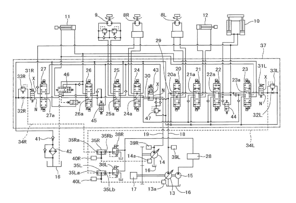
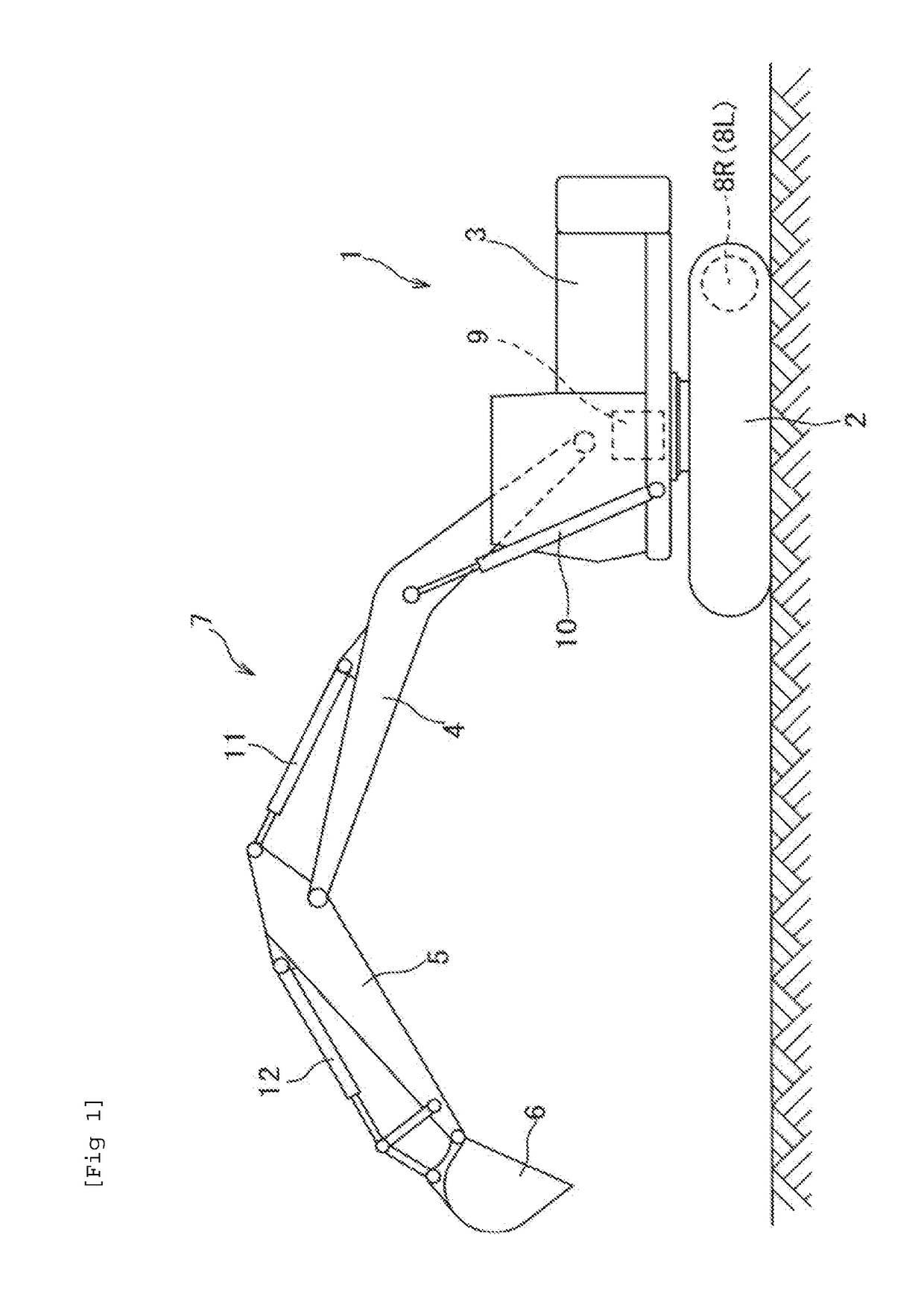
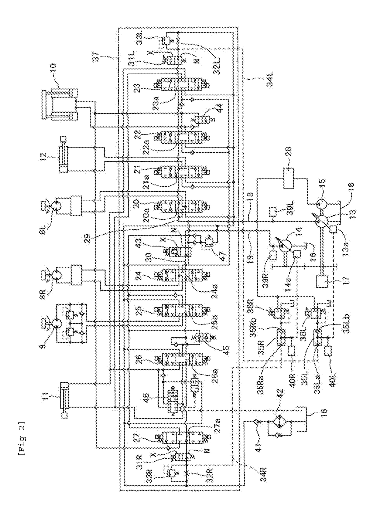
[0040]Hereinafter, an embodiment of the present invention will be described with reference to the accompanying drawings. FIG. 1 is a diagram illustrating a hydraulic shovel 1 which is an example of a hydraulic working machine of the present invention. The hydraulic shovel 1 is configured with an upper turning body 3 turnably supported above a crawler type lower traveling body 2, and a front working portion 7 including a boom 4, an arm 5 and a bucket 6 mounted on the upper turning body 3. Further, the hydraulic shovel 1 is configured to include left and right traveling motors 8L and 8R which drive the lower traveling body 2, a turning motor 9 which drives the upper turning body 3, and various hydraulic actuators such as a boom cylinder 10, an arm cylinder 11 and a bucket cylinder 12 which move the boom 4, the arm 5 and the bucket 6, respectively.

[0041]FIG. 2 is a diagram illustrating a hydraulic circuit provided in the hydraulic shovel 1, and a hydraulic pump control system of the pr...


PUM


Abstract

A hydraulic working machine is provided that uses a variable displacement pump and open center type flow rate control valve for a controlling a hydraulic actuator, and has a negative control throttle disposed in a center bypass oil passage to generate a negative control pressure. A hydraulic pump control system performs virtual bleed-off control for reducing the bleed-off flow rate of the center bypass oil passage, and can operate the hydraulic actuator with the same performance as an open center control. The control system includes a bypass cut valve disposed upstream from the negative control throttle to reduce flow through the center bypass oil passages, and a negative control pressure output valve that outputs a virtual negative control pressure. The control system is configured to reduce the bleed-off flow rate by operating the bypass cut valve when virtual bleed-off control is performed, and to reduce the pump flow rate by the bleed-off reduction flow rate.

Description

TECHNICAL FIELD[0001]The present invention relates to a technical field of a hydraulic pump control system of a hydraulic working machine such as a hydraulic shovel.BACKGROUND ART[0002]In general, in a hydraulic circuit provided in a hydraulic working machine such as a hydraulic shovel, an open center control system is widely known in the related art. An open center control system is equipped with a variable displacement hydraulic pump, an open center type flow rate control valve configured to control a supply flow rate to a hydraulic actuator from the hydraulic pump, a center bypass oil passage extending from the hydraulic pump to the oil tank via a bleed-off opening of the flow rate control valve. A negative control throttle is disposed on the center bypass oil passage on the downstream side of the bleed-off opening to generate a negative control pressure, and is configured to perform increase and decrease control of the pump flow rate of the hydraulic pump in accordance with the ...

Claims


Application Information

Patent Timeline
Patent Type & Authority Applications(United States)
IPC IPC(8): E02F9/22F15B11/16
CPCE02F9/2228E02F9/2296E02F9/2267E02F9/2271E02F9/2282E02F9/2235F15B11/165E02F9/2292E02F9/2232F15B2211/20553F15B2211/20576F15B2211/3116F15B2211/40507F15B2211/40515F15B2211/41554F15B2211/426F15B2211/45F15B2211/50518F15B2211/5156F15B2211/7135F15B2211/7142E02F9/2242F15B11/166
Inventor KISHIDA, KOUJIHATA, YOSHIHIKOMATOBA, NOBUAKI
Owner CATEPILLAR SARL
Why Eureka
Try Eureka