Clustering system

Inactive Publication Date: 2006-08-17
HITACHI SOFTWARE ENG
View PDF4 Cites 29 Cited by
  • Summary
  • Abstract
  • Description
  • Claims
  • Application Information

AI Technical Summary

Benefits of technology

[0013] It is therefore an object of the invention to provide a technique whereby the structure of a clustering result obtained by the SOM can be visualized by ca

Problems solved by technology

However, it is difficult to visually determine which of the cells that are adjacent a particular cell is most similar to the particular cell.
Furt

Method used


Image

  • Clustering system
  • Clustering system
  • Clustering system

Examples


Embodiment Construction

[0027] An embodiment of the invention will be hereafter described by referring to the drawings.

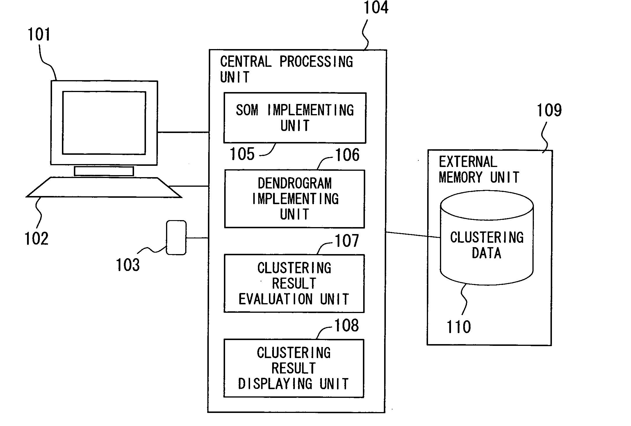
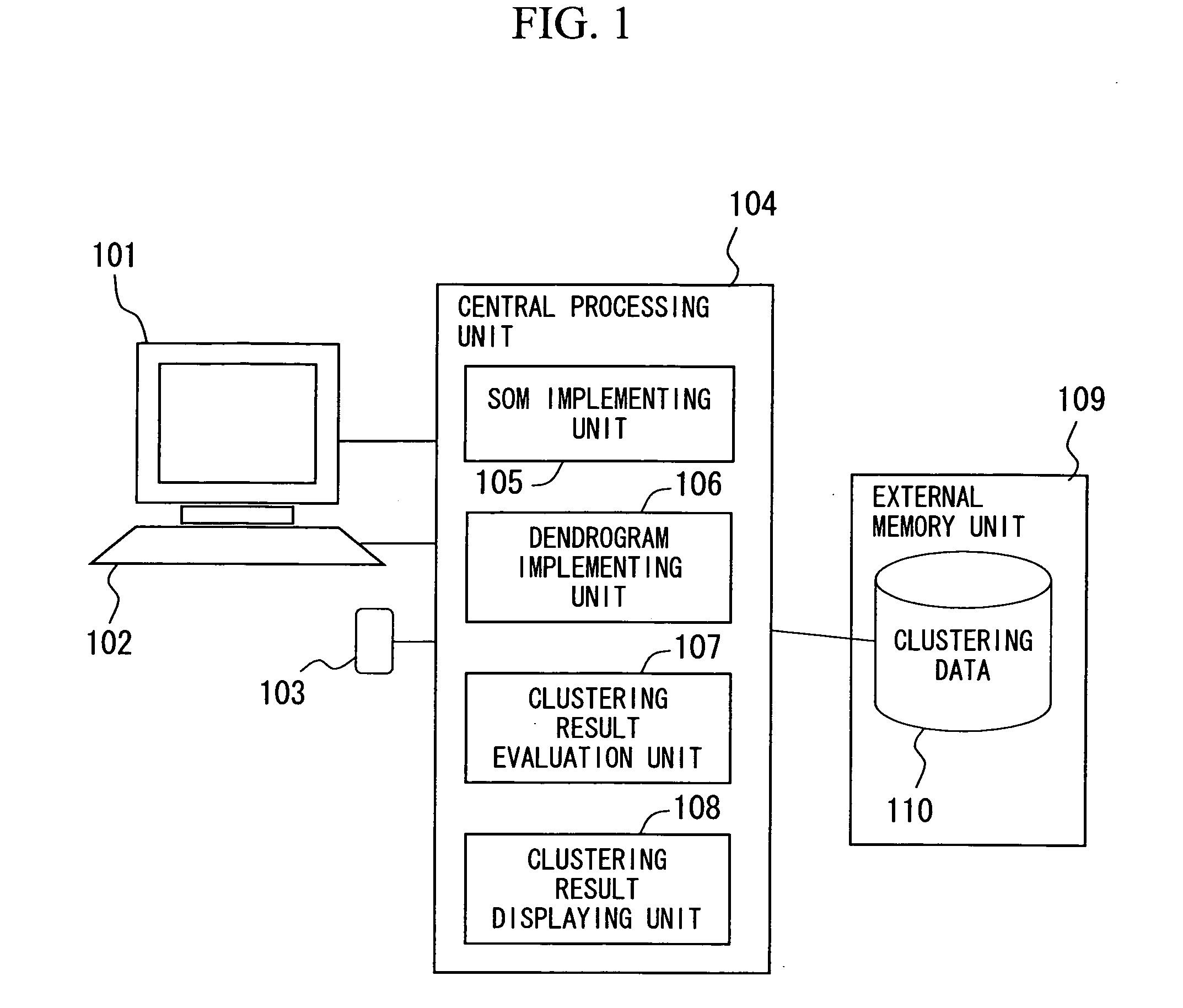
[0028]FIG. 1 shows the system structure of an embodiment of the invention. The system includes a central processing unit 104 for the calculation and evaluation for clustering as well as the display of their results, a display unit 101 having a character and graphic screen, a keyboard 102, mouse 103, and an external memory unit 109 for storing clustering data 110. The central processing unit 104 includes a SOM implementing unit 105, a dendrogram implementing unit 106, a clustering result evaluating unit 107, and a clustering result displaying unit 108. The SOM implementing unit 105, the dendrogram implementing unit 106, the clustering result evaluating unit 107, and the clustering result displaying unit 108 can all be realized using programs.

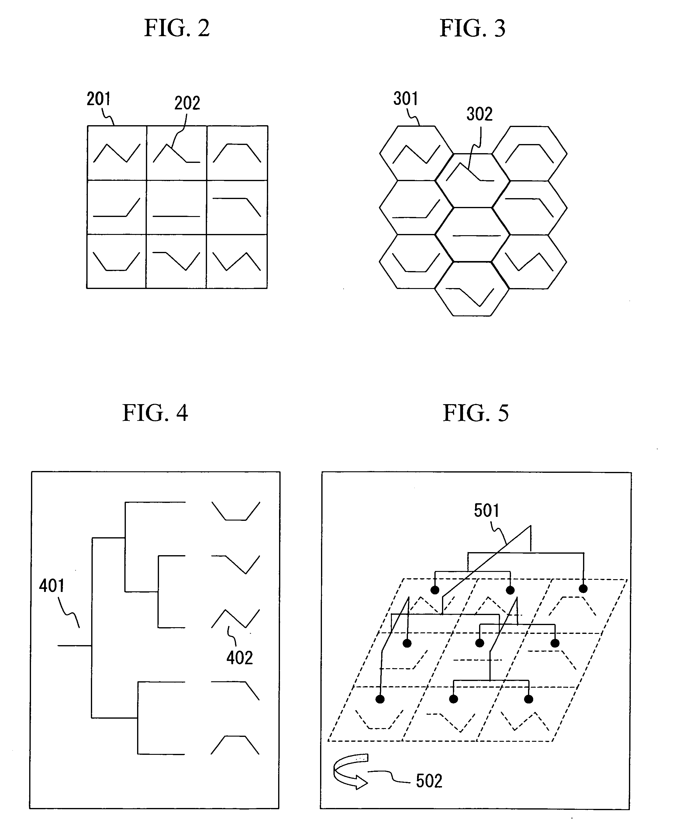
[0029] The SOM implementing unit 105 receives clustering data and algorithm setting parameters and then performs clustering by the SOM method. For th...


PUM

PropertyMeasurementUnit
Coloraaaaaaaaaa
Shapeaaaaaaaaaa
Levelaaaaaaaaaa

Abstract

A group of cells are newly clustered on the basis of the result of implementing a SOM. A plurality of pieces of multivariate data are clustered via a SOM, and cells are displayed on a two-dimensional plane as rectangular or hexagonal shapes. The level of similarity between representative vectors from each adjacent cell is calculated, and a dendrogram is three-dimensionally depicted. Cells on a SOM map are colored differently in accordance with a plane for partitioning the dendrogram.

Description

CLAIM OF PRIORITY [0001] The present application claims priority from Japanese application JP 2004-355214 filed on Dec. 8, 2004, the content of which is hereby incorporated by reference into this application. BACKGROUND OF THE INVENTION [0002] 1. Field of the Invention [0003] The present invention relates to a clustering system for displaying the results of clustering in a visually easily recognizable manner using a combination of clustering techniques involving a SOM (self-organizing map) and a dendrogram. [0004] 2. Background Art [0005] Conventionally, the SOM (self-organizing map) (T. Kohonen, “Self-Organizing Maps,” Springer 1995) has been used as a clustering technique for grouping a plurality of items of multivariate data by calculating the similarity between them in terms of the Euclidean distance (simple geometric distance in a multidimensional space) or the Manhattan distance (distance expressed in terms of simple difference in each dimension). The SOM, which is one of non-...

Claims


Application Information

Patent Timeline
IPC IPC(8): G06N3/12C12N15/09G06F17/30G06F19/00G06F19/24
CPCG06K9/6219G06K9/6251G06K9/6253G06N3/088G06F18/231G06F18/2137G06F18/40
Inventor MORI, ATSUSHI
Owner HITACHI SOFTWARE ENG
Why Eureka
Try Eureka