
Energy status indicator in a portable device

a portable device and energy status technology, applied in the field of electronic portable devices, can solve the problems of inconvenience, inability to choose and user is not offered the option of choosing a different type of warning

Inactive Publication Date: 2006-08-24
BENQ CORP
View PDF8 Cites 172 Cited by
  • Summary
  • Abstract
  • Description
  • Claims
  • Application Information

AI Technical Summary

Benefits of technology

[0015] It is therefore a primary objective of the invention to provide an energy status indicator that solves the above-mentioned problems of the prior art.

Problems solved by technology

Unfortunately, the prior art's energy status indicator, as well as the manner in which is employed within the portable device's framework, has a few serious drawbacks.
As a result, the user is not offered the option of choosing a different type of warning.
This is an inconvenience which can be especially felt when the user voluntarily desires to verify the battery status.
He may be unable to do so for a variety of reasons which could be either user or device induced.
The device induced reasons can be that the day is very sunny preventing the user from discerning what is being displayed or that the portable device's display is broken.

Method used


Image

  • Energy status indicator in a portable device
  • Energy status indicator in a portable device
  • Energy status indicator in a portable device

Examples


Embodiment Construction

[0024] Please refer to FIG. 3 which depicts a conventional ‘flip’ cellular phone 300. The ‘flip’ cellular phone 300 comprises an upper part 302, a lower part 304 and a mechanical activation sensor 306.

[0025] The ‘flip’ cellular phone 300 is in closed position A as determined by the upper part 302 horizontally hugging the lower part 304. In closed position A, the mechanical activation sensor 306 has not been triggered causing the phone to remain inactivate.

[0026] The ‘flip’ cellular phone 300 is in open position B as determined by the upper part 302 being separated from lower part 304 by a certain distance. In open position B, the mechanical activation sensor 306 is mechanically triggered by the separation of upper part 302 from lower part 304, causing the phone to become activated.

[0027] Please refer to FIG. 4 which illustrates a conventional ‘non-flip’ cellular phone 400. The ‘non-flip’ cellular phone 400 includes an electromagnetic activation sensor 402 and keys 404.

[0028] The...


PUM


Abstract

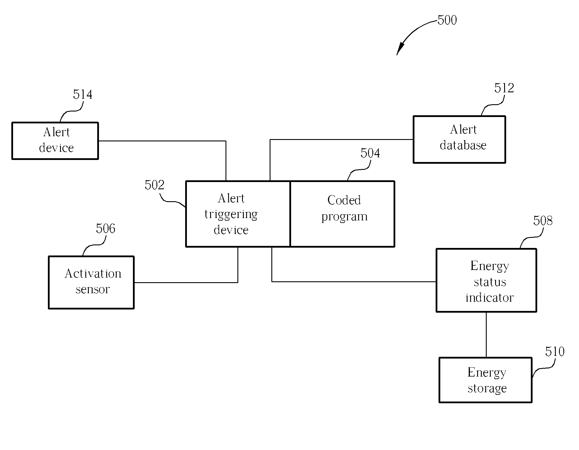
An energy status indicator for a portable device includes an alert device, an activation sensor, an energy status indicator, an alert triggering device and an alert database that includes alert data. The activation sensor is for detecting if the portable device is activated and the energy status indicator is used for determining a level of remaining energy in an energy storage. The alert triggering device includes coded program which is for outputting alert data corresponding to the level of remaining energy through the alert device, after the portable device's activation. The energy status indicator gives a user control over when the energy status is to be output and also to the type of alert that is to be output (e.g. sound, vibration, etc.). Additionally, it allows the user to determine the energy status when visual inspection of the portable device is not possible.

Description

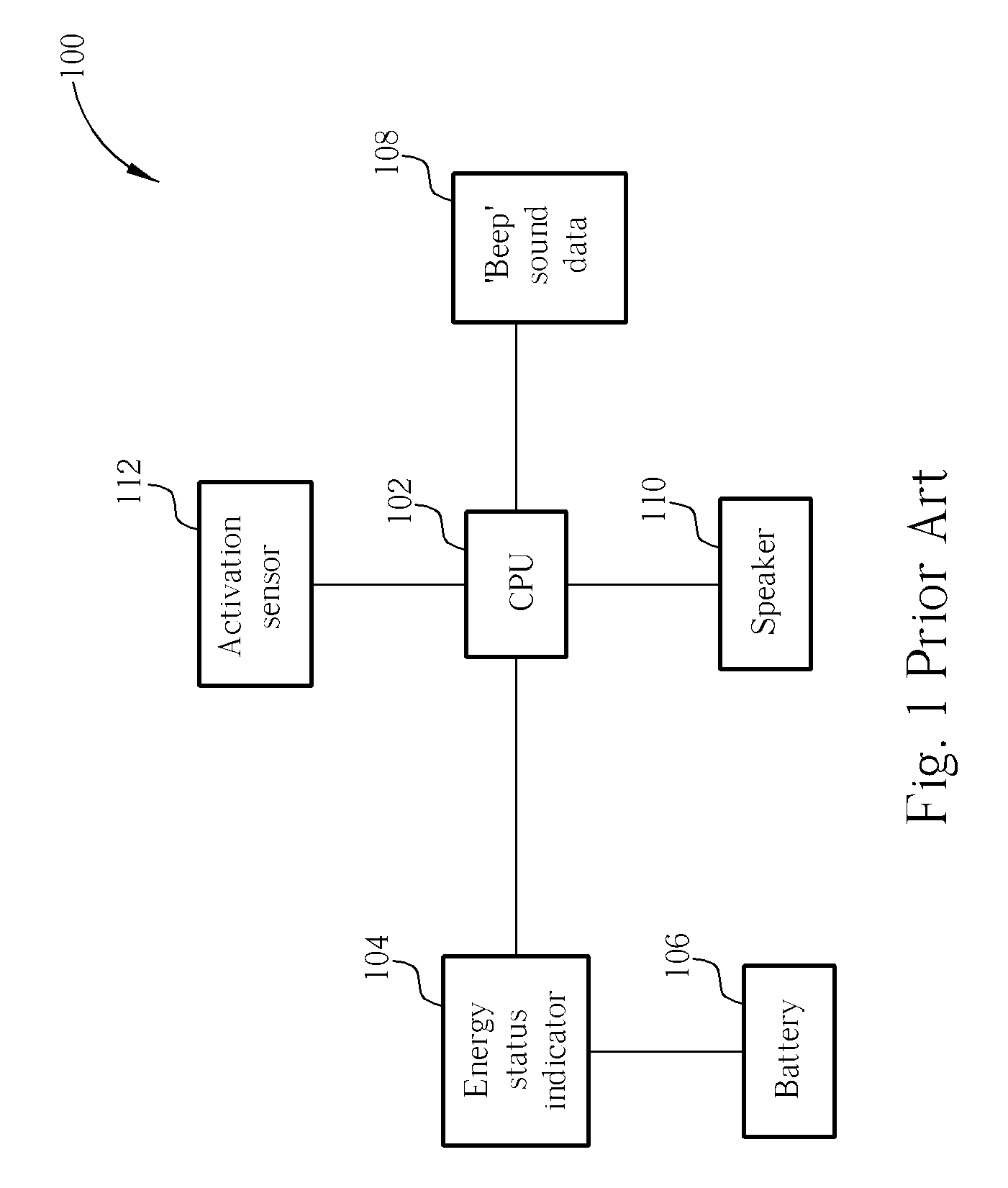
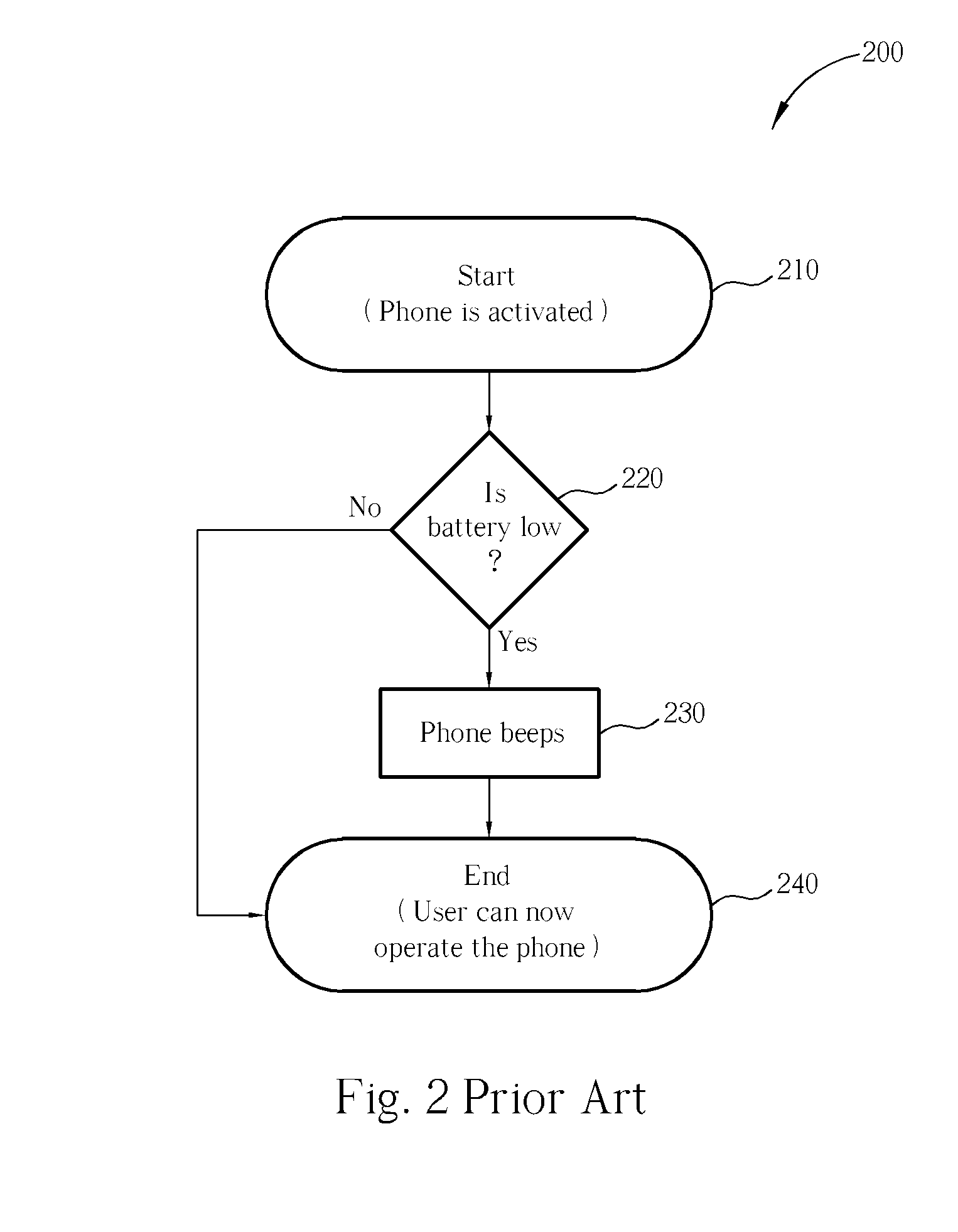
BACKGROUND OF INVENTION [0001] 1. Field of the Invention [0002] The present invention relates to an electronic portable device, and more specifically, to an energy status indicator in a portable device. [0003] 2. Description of the Prior Art [0004] Nowadays, portable devices such as cellular phones or PDAs are becoming ever more popular. Due to their increased popularity, manufacturers are continuously developing various new features in an attempt to provide more useful functionality to these portable devices. One of these features is the energy status indicator, whose task is to indicate the amount of energy left in the device's energy storage. [0005] The prior art explains the workings of the energy status indicator as being very simple—if the energy status indicator detects that the energy remaining in the energy storage is low then the portable device beeps. [0006] Please refer to FIG. 1, which illustrates the prior art logic associated with generating an audible low battery ind...

Claims


Application Information

Patent Timeline
IPC IPC(8): G08B21/00H02J7/00
CPCG01R31/3648G01R31/3682H01M10/48H01M10/488H04M1/72519H04W52/0254H04W52/0277G01R31/3646Y02E60/10H04M1/724Y02D30/70
Inventor LIN, CHAO-HUASU, IVAN
Owner BENQ CORP
Learn More