CMOS silicide metal gate integration

a metal gate and silicide technology, applied in the direction of transistors, semiconductor devices, electrical equipment, etc., can solve problems such as non-uniform performance, and achieve the effect of reducing processing complexity and not increasing the production cost of cmos transistors

Inactive Publication Date: 2006-08-24
AURIGA INNOVATIONS INC
View PDF19 Cites 15 Cited by
  • Summary
  • Abstract
  • Description
  • Claims
  • Application Information

AI Technical Summary

Benefits of technology

[0012] In a first embodiment of the present invention, a CMOS silicide metal gate integration approach that does not have the shortcomings of variations in the polySi gate stack height which lead to variations in the silicide metal gate phases that form is provided. The integration approach of the present invention keeps the processing complexity to a minimum thereby not increasing the production cost of CMOS transistors.

Problems solved by technology

This leads to non-uniform performance.

Method used


Image

  • CMOS silicide metal gate integration
  • CMOS silicide metal gate integration
  • CMOS silicide metal gate integration

Examples


first embodiment

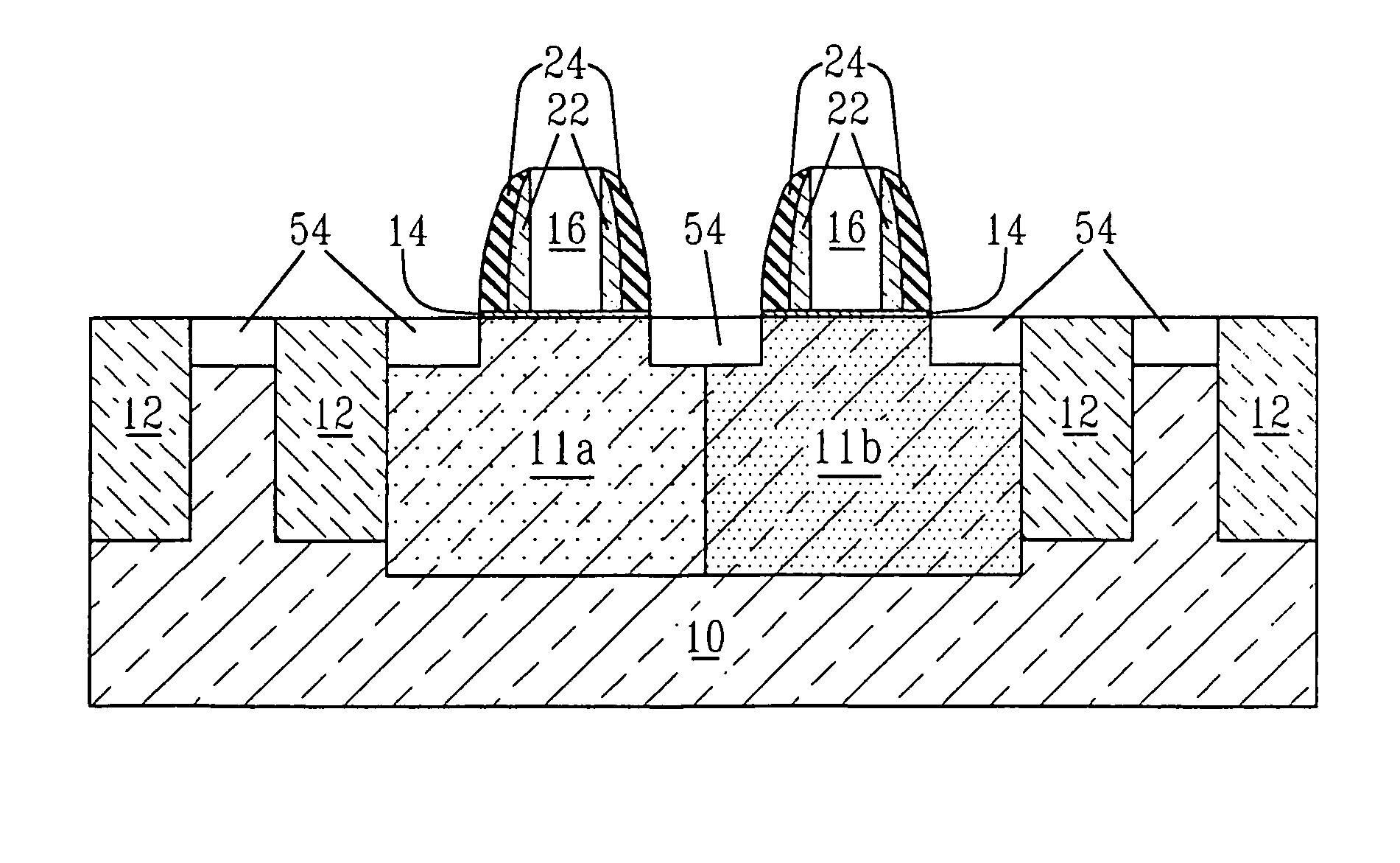
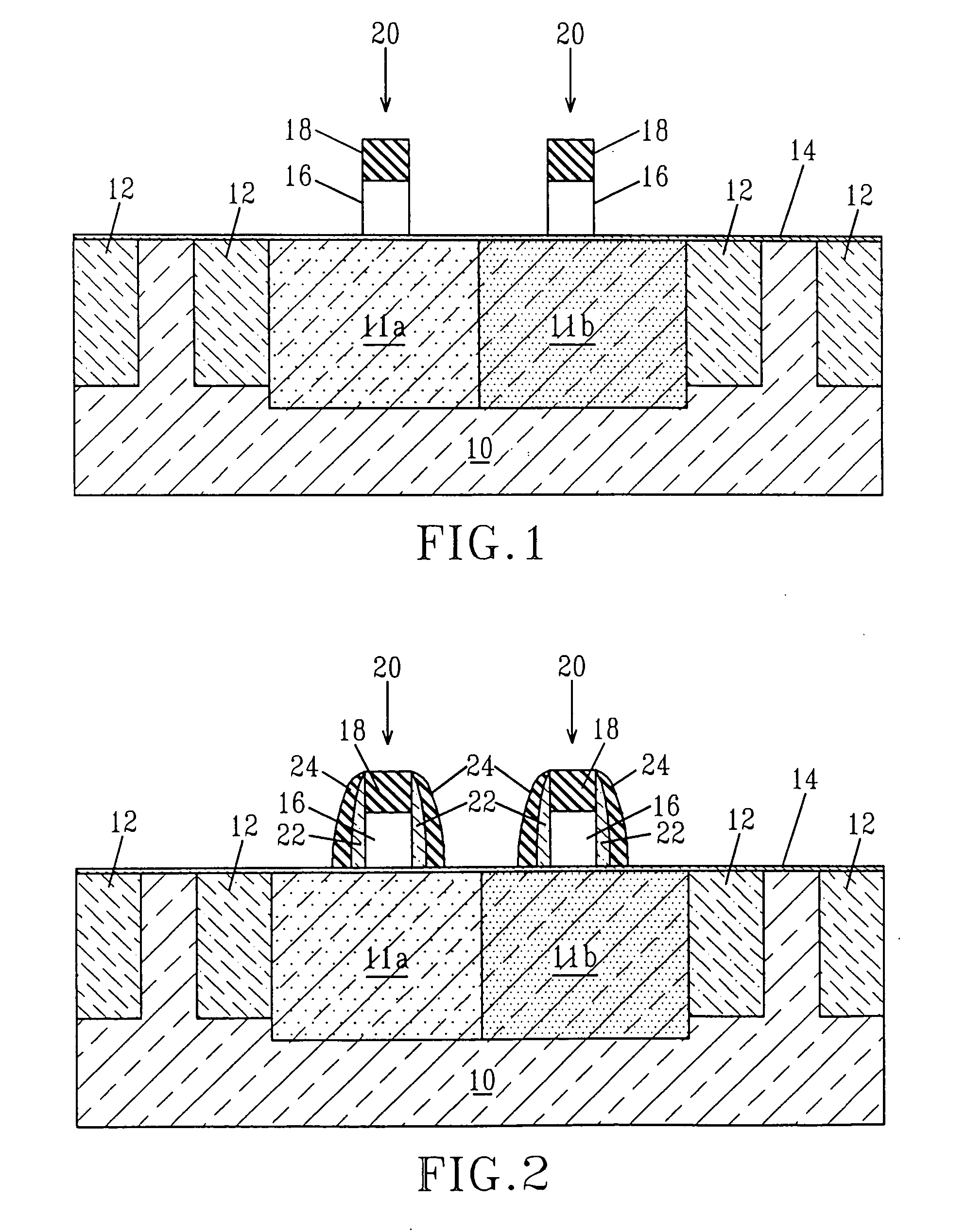
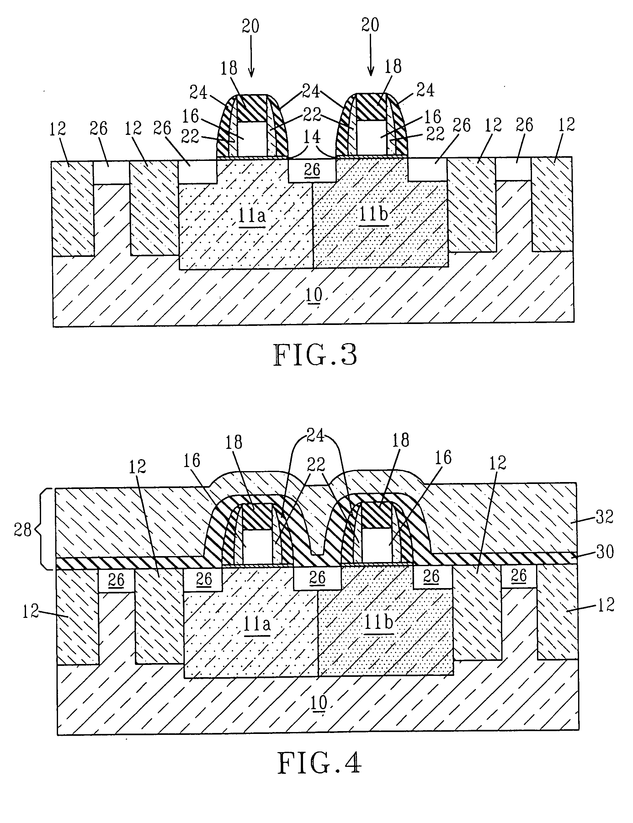
[0054] Reference is made to FIGS. 1-10, which are cross sectional views of a CMOS structure during various stages of the present invention. Although the drawings show the presence of two polySi gates (i.e., a CMOS transistor structure with pFET and nFET transistors), the present invention is not limited to that number of polySi gates. Instead, the present integration process works for any number of polySi gates. Hence, a plurality of polySi gates may be present across a single semiconductor structure.

[0055]FIG. 1 shows an initial structure that is employed in the first embodiment of the present invention. Specifically, the initial structure shown in FIG. 1 comprises semiconductor substrate 10 having isolation regions 12 formed therein. The initial structure also includes a gate dielectric 14 located on top of the semiconductor substrate 10 as well as on top of the isolation regions 12. This is the case if the dielectric is deposited as for a high k material, but not if the dielectri...

second embodiment

[0091] Reference is made to FIGS. 11A-11E, which are cross sectional views of a CMOS structure during various stages of the present invention. Although these drawings show the presence of two polySi gates (i.e., a CMOS transistor structure with pFET and nFET transistors), the present invention is not limited to that number of polySi gates. Instead, the present integration process works for any number of polySi gates. Hence, a plurality of polySi gates may be present across a single semiconductor structure.

[0092]FIG. 11A shows an initial structure that can be employed in the second embodiment of the present invention. As shown, the initial structure includes a semiconductor substrate 10, patterned gate dielectric 14 located on a surface of the semiconductor substrate 10, a patterned polySi gate 16 located atop a surface portion of the patterned gate dielectric 14 and spacers 23 formed on exposed vertical sidewalls of each patterned polySi gate16. The structure shown in FIG. 11A inclu...

third embodiment

[0103] Reference is made to FIGS. 12A-12F, which are cross sectional views of a CMOS structure during various stages of the present invention. Although these drawings show the presence of two polySi gates (i.e., a CMOS transistor structure with pFET and nFET transistors), the present invention is not limited to that number of polySi gates. Instead, the present integration process works for any number of polySi gates. Hence, a plurality of polySi gates may be present across a single semiconductor structure.

[0104]FIG. 12A shows an initial CMOS structure that can be employed in the second embodiment of the present invention. As shown, the initial structure includes a semiconductor substrate 10 having first doped region 11a, second doped region 11b and isolation regions 12 formed therein, patterned gate dielectric 14 located on a surface of the semiconductor substrate 10, a patterned polySi gate 16 located atop a surface portion of the patterned gate dielectric 14 and spacers 22 and 24 ...


PUM

PropertyMeasurementUnit
temperatureaaaaaaaaaa
heightaaaaaaaaaa
heightaaaaaaaaaa

Abstract

The present invention provides a complementary metal oxide semiconductor integration process whereby a plurality of silicided metal gates are fabricated atop a gate dielectric. Each silicided metal gate that is formed using the integration scheme of the present invention has the same silicide metal phase and substantially the same height, regardless of the dimension of the silicide metal gate. The present invention also provides various methods of forming a CMOS structure having silicided contacts in which the polySi gate heights are substantially the same across the entire surface of a semiconductor structure.

Description

RELATED APPLICATIONS [0001] This application is a divisional of U.S. application Ser. No. 10 / 786,901, filed Feb. 25, 2004.FIELD OF THE INVENTION [0002] The present invention relates to the fabrication of circuit devices on semiconductor substrates, and more particularly to a complementary metal oxide semiconductor (CMOS) transistor fabrication method for forming silicide metal gates that have substantially the same height. The present invention is also related to a method of forming silicided source / drain regions without effecting the height of the polysilicon gate conductor. BACKGROUND OF THE INVENTION [0003] Throughout the prior art, metal gate integration has proven difficult to achieve in a conventional process flow for CMOS transistors. Most metal gate materials interact with the gate dielectric during the high temperature processing needed for source / drain (S / D) junction activation anneals. The need to keep the metal gate stack from receiving high temperature anneals has lead ...

Claims


Application Information

Patent Timeline
Patent Type & Authority Applications(United States)
IPC IPC(8): H01L21/8238H01L21/28H01L21/336H01L21/339H01L21/60
CPCH01L21/28052H01L21/28097H01L29/6656H01L21/823835H01L29/66545H01L21/76897H01L27/092H01L21/8238
Inventor AMOS, RICKY S.BOYD, DIANE C.CABRAL, CYRIL JR.KAPLAN, RICHARD D.KEDZIERSKI, JAKUB T.KU, VICTORLEE, WOO-HYEONGLI, YINGMOCUTA, ANDA C.NARAYANAN, VIJAYSTEEGEN, AN L.SURENDRA, MAHESWAREN
Owner AURIGA INNOVATIONS INC
Why Eureka
Try Eureka