Camera module connector

a technology for camera modules and connectors, applied in the direction of coupling device connections, coupling protective earth/shielding arrangements, connection contact member materials, etc., can solve the problems of difficult cost reduction, high labor intensity, and inconvenient manufacturing of shielding housings, so as to reduce the need for manpower and reduce assembly time, the effect of improving the shielding

Inactive Publication Date: 2006-08-24
MOLEX INC
View PDF15 Cites 47 Cited by
  • Summary
  • Abstract
  • Description
  • Claims
  • Application Information

AI Technical Summary

Benefits of technology

[0009] It is therefore a general object of the present invention to provide a camera module connector, which can provide shielding for a camera module and an electrical connector with a better shielding and protective effect and a method of manufacture that is easier and reduces the need for manpower and lessens assembly time to reduce costs effectively, and is also slim and light.
[0010] Another object of the present invention is to provide an improved camrea module and connector assembly, wherein the exterior surfaces of the camera module are plated with a conductive material so as to provide shielding to the camera module, and wherein the connector is configured to receive the module therein.
[0014] The present invention is coated with a conductive layer, preferably a metal plating, on the main body of the camera module, so that it provides shielding to the camera module and the electrical connector for protection from EMI. The metal layer is coated on the main body of the camera module. Thus, the camera module connector assembly may manufactured more simply and less labor and time is required during assembly to thereby reduce its cost. Moreover, the metal layer is coated on the main body of the camera module, and the total size is not increased much at all.

Problems solved by technology

The manufacturing of the shielding housing 9 is quite inconvenient, and the finished shielding housing 9 requires further assembling with the camera module 7 and the electrical connector 6.
The assembly thereof requires much time and work, so it is difficult to reduce costs.
Moreover, the shielding housing 9 is assembled on the camera module 7 and the electrical connector 6, which also increases the entire size and is difficult to fulfill the smaller-size requirements of new, then and light electronic products.

Method used


Image

  • Camera module connector
  • Camera module connector
  • Camera module connector

Examples


Embodiment Construction

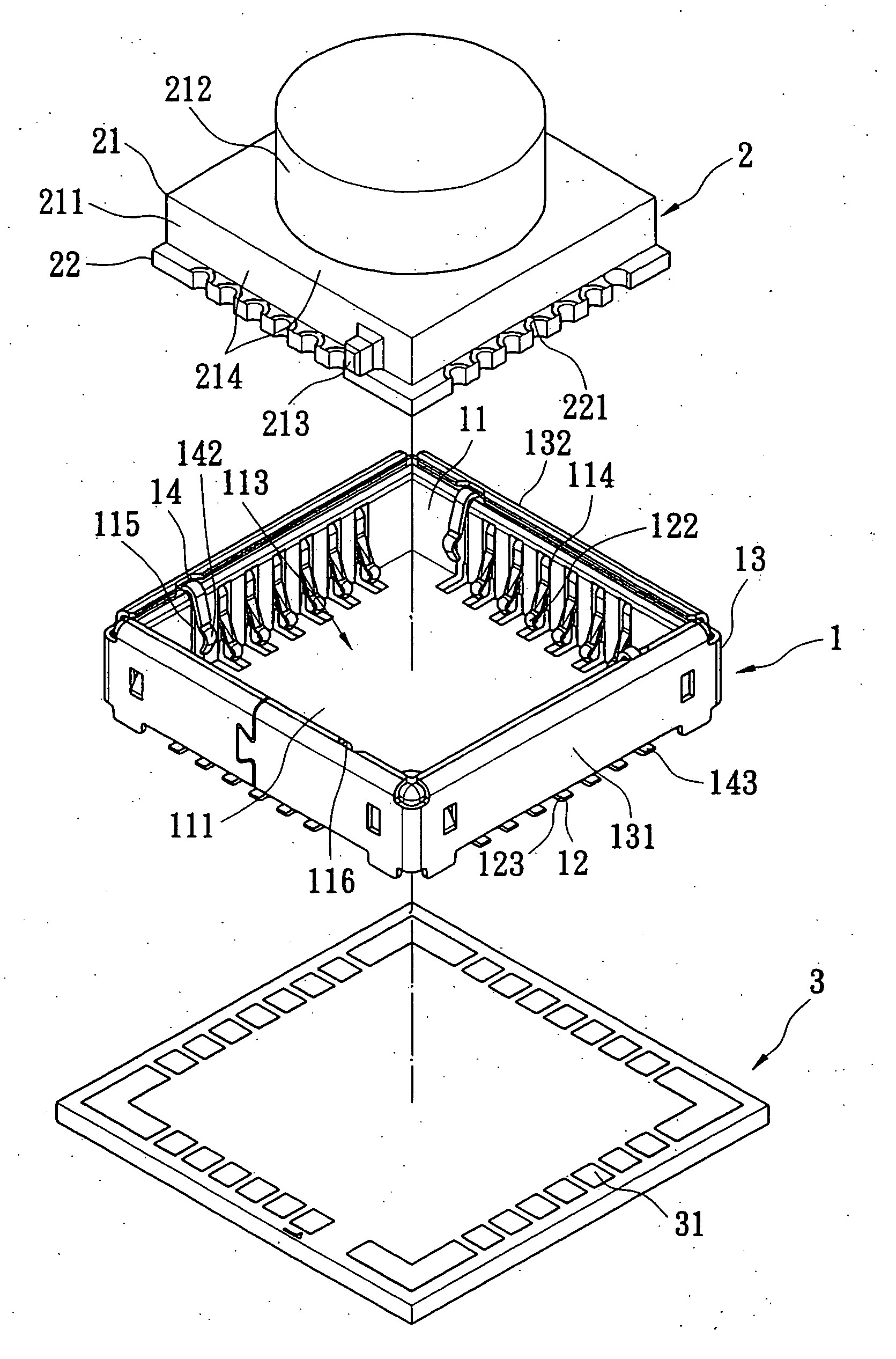
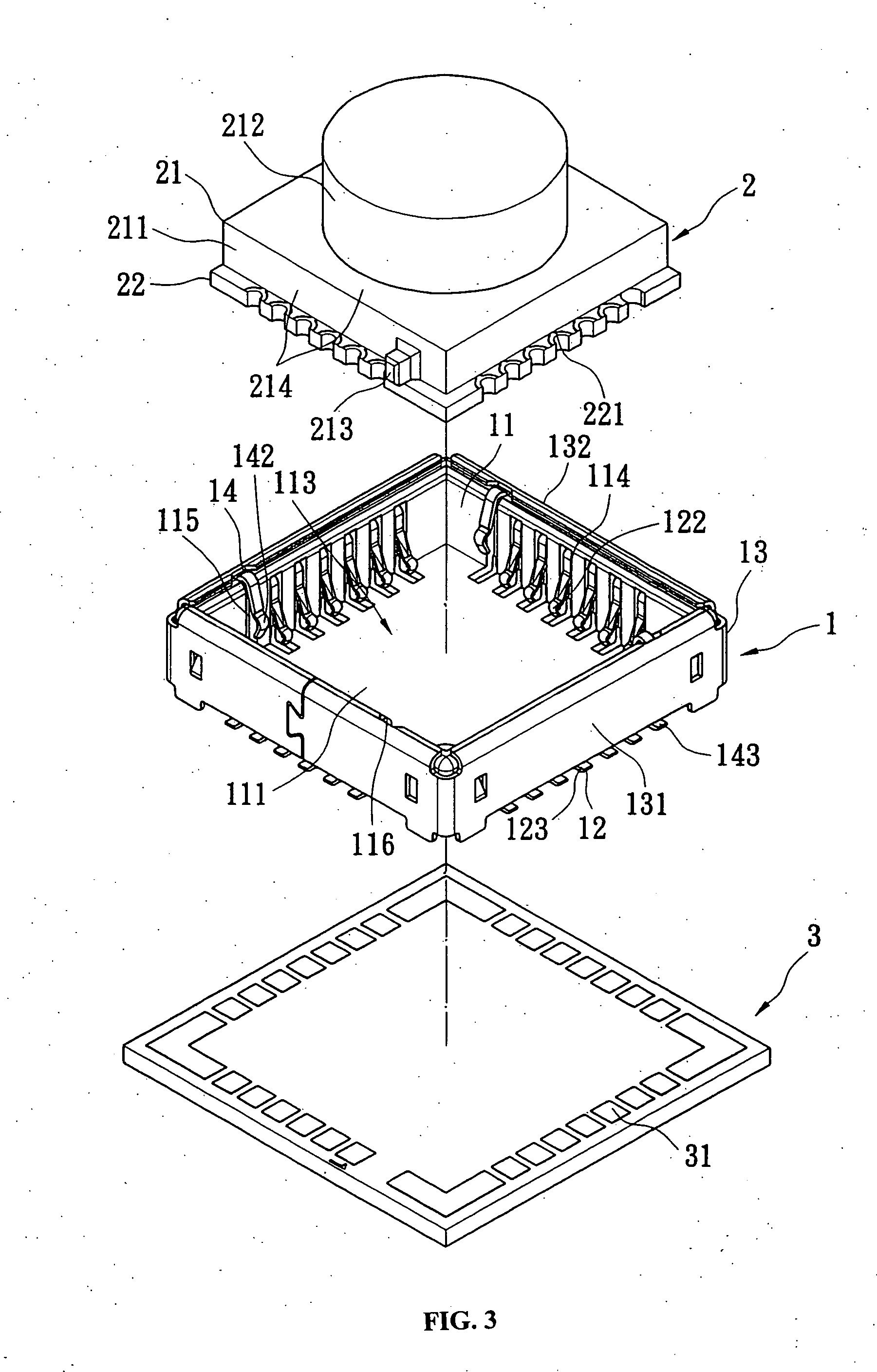
[0026] Referring to FIGS. 3 to 7, it can be seen that the present invention provides a camera module connector, which includes an electrical connector 1 and a camera module 2. The electrical connector 1 is mounted on a circuit board 3 for receiving the camera module 2 therein.

[0027] The electrical connector 1 includes an insulative housing 11, a plurality of conductive signal terminals 12 supported therein, a conductive metallic or metal housing 13 and at least one grounding pin 14. The housing 11 is made of plastic and has a bottom wall 111 and four side walls 112 formed integrally with the bottom wall 111 (as shown in FIG. 8). A receiving space 113 is formed between the bottom wall 111 and the four side walls 112 of the housing 11. The four side walls 112 of the housing 11 are formed with a plurality of terminal-receiving grooves or cavities 114. The grooves 114 penetrate through an outside edge connecting the side walls 112 and the bottom wall 111. The terminal grooves 114 also ...


PUM


Abstract

A camera module connector assembly includes a connector and a camera module. The connector includes an insulative housing that defines a hollow receiving space therein, a plurality of signal terminals fixed in the housing, a shield surrounding the housing, and at least one grounding pin. The camera module is disposed in the receiving space and has a substrate formed with contact pads. One end of each of the terminals respectively contact the substrate contact pads, so that the camera module is electrically connected to the connector. A metal layer is coated on the main body of the camera module, which provides a shielding function to the camera module and the connector, to protect the present invention from EMI for a better shielding result. The camera module assembly is manufactured more easily for reducing manpower and time, thereby the assembling cost is also reduced.

Description

BACKGROUND OF THE INVENTION [0001] The present invention relates to a camera module connector, and more particularly, to a camera module connector having an electrical connector for receiving a camera module therein to make the camera module electrically connect with a circuit board, and wherein the camera moduoe has a grounding aspect integrated therewith. [0002] Because of the development of wireless communication and the rapid revolution in high technology, portable electronic products, such as mobile phones, PDAs and Tablet PCs, are assembled with different electronic additional-modules such as camera modules for taking pictures and satisfying desires of consumers. [0003] Reference is now made to FIGS. 1 and 2, which illustrate a conventional camera module connector including an electrical connector 6 and a camera module 7. The electrical connector 6 is mounted on a circuit board 8 for accommodating the camera module 7. [0004] The electrical connector 6 includes an insulative ca...

Claims


Application Information

Patent Timeline
Patent Type & Authority Applications(United States)
IPC IPC(8): H01R13/648H01R12/14H01R13/658H01R24/58
CPCH01R13/5025H01R13/65802H01R24/58H01R2107/00H01R12/716H01R13/6583H01R13/6594
Inventor YANG, MING-HSUN
Owner MOLEX INC
Why Eureka
Try Eureka