
MSA transceiver testing device and interface for use therewith

a transceiver and testing device technology, applied in the direction of transmitter monitoring, receiver monitoring, electrical equipment, etc., can solve the problems of complex testing and measurement devices, over-sophisticated for most testing procedures performed in a manufacturing environment, and large capital expenditure of the manufacturer of msa transceivers

Inactive Publication Date: 2006-08-24
DAITO PRECISION
View PDF0 Cites 39 Cited by
  • Summary
  • Abstract
  • Description
  • Claims
  • Application Information

AI Technical Summary

Problems solved by technology

As such, manufacturers of MSA transceivers spend a considerable amount of capital on purchasing and using various test and measurement devices.
A deficiency with existing test and measurement devices is that they are generally designed and built for research and development purposes, which means that they are often over-sophisticated for most testing procedures performed in a manufacturing environment.
A further deficiency with existing testing and measurement devices is their complexity.
This complexity contributes to the overall complexity of the manufacturing production line, which can lead to increased downtime when things malfunction.
A still further deficiency with existing test and measurement set ups is that they are generally formed of an assembly of off-the-shelf test units, such as power meters and oscilloscopes that are assembled together, and that are only able to test one aspect of the MSA transceivers at a time.

Method used


Image

  • MSA transceiver testing device and interface for use therewith
  • MSA transceiver testing device and interface for use therewith
  • MSA transceiver testing device and interface for use therewith

Examples


Embodiment Construction

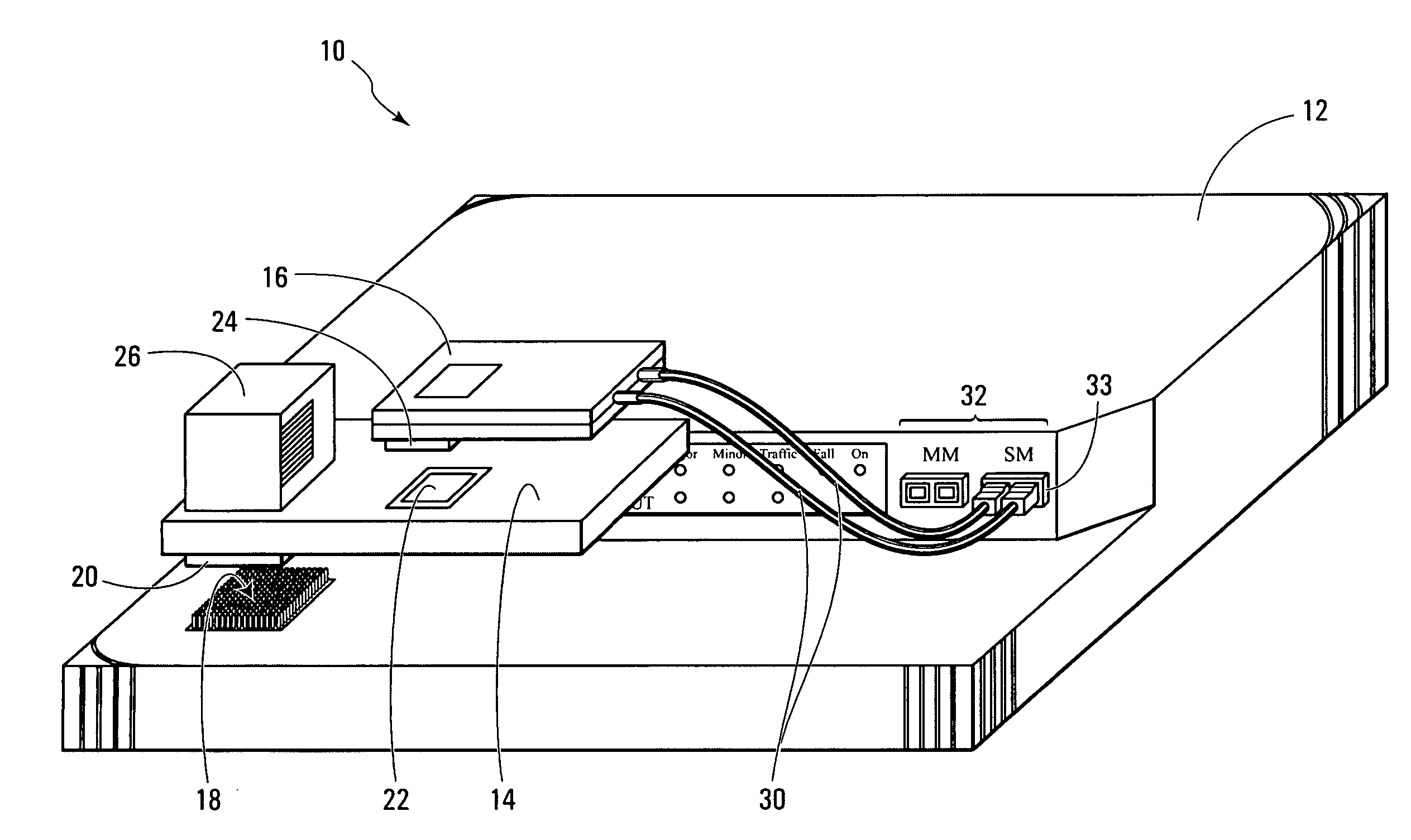
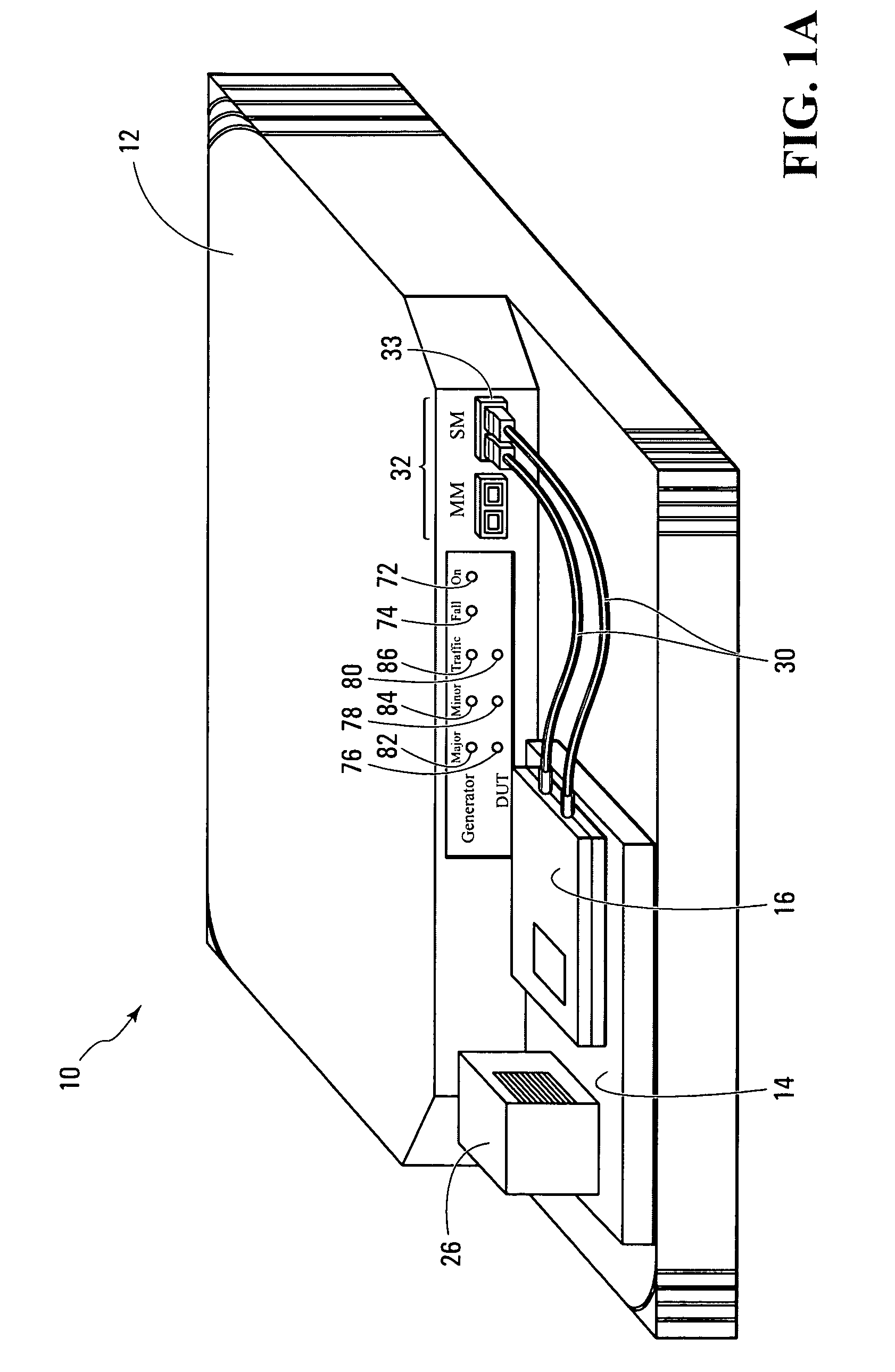
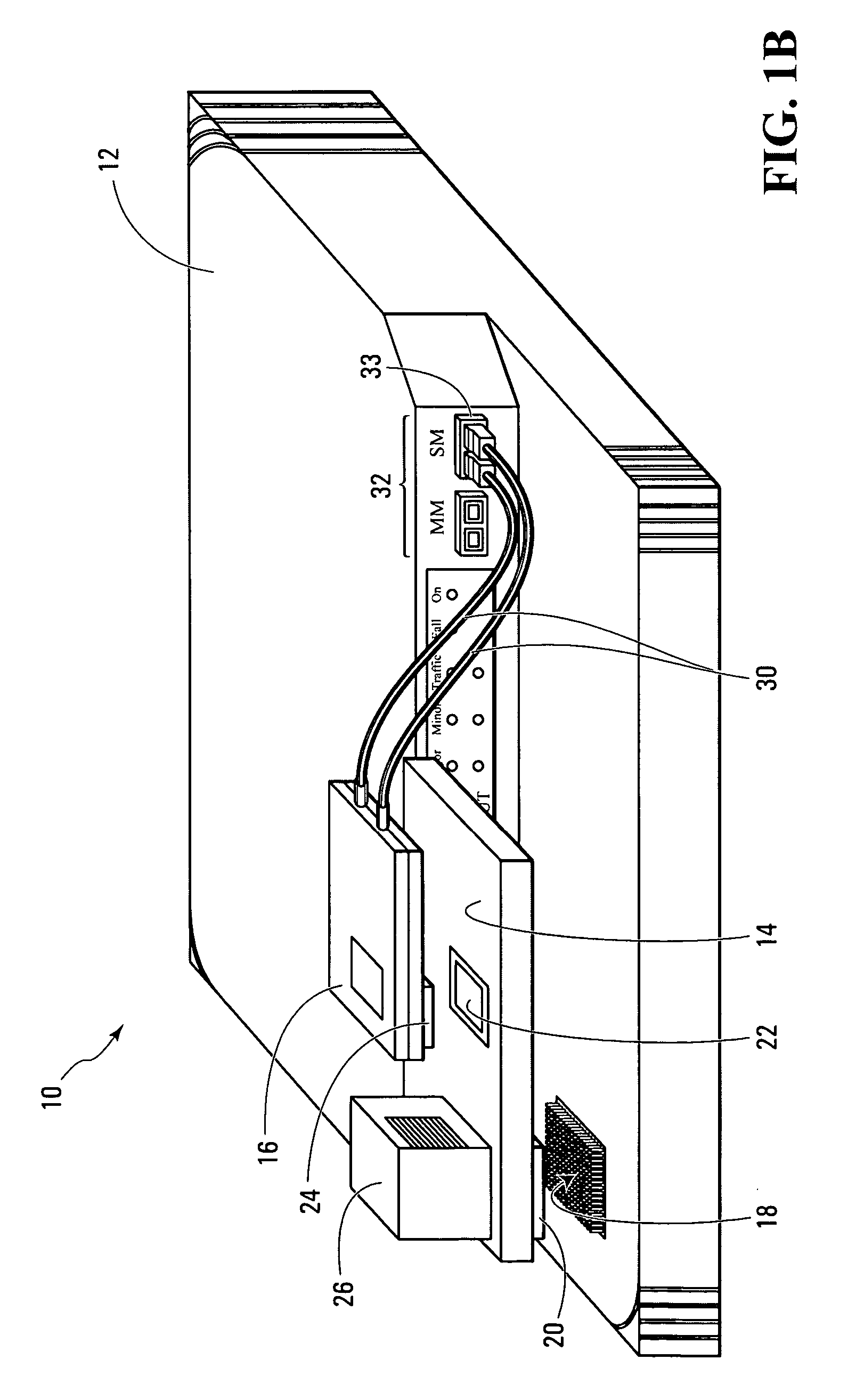
[0024] Shown in FIGS. 1A and 1B is a transceiver testing system 10 in accordance with a non-limiting example of implementation of the present invention. The transceiver testing system 10 is operative for testing transceiver modules that adhere to different multi-source agreement (MSA) standards. As shown, the transceiver testing system 10 includes a transceiver testing device 12, and at least one interface connection unit 14 for connecting an MSA transceiver module, such as MSA transceiver module 16, to the transceiver testing device 12.

[0025] In accordance with the present invention, the transceiver testing device 12 is operative for testing transceiver modules that adhere to different MSA standards. In this manner, only one transceiver testing device 12 is required for performing testing on transceiver modules belonging to different MSA standards. Some non-limiting examples of the most popular optical and electrical MSA transceiver standards include Small Form Factor (SFF), Small...


PUM


Abstract

A system for testing transceiver modules associated to different multi-source agreement standards, comprising a transceiver testing device and an interface connection unit. The transceiver testing device comprises a processor for performing at least one testing operation on an MSA transceiver module associated to a certain multi-source agreement standard. The interface connection unit is suitable for connecting the MSA transceiver module to the transceiver testing device. The transceiver module includes a certain type of electrical connector element. The interface connection unit comprises a first connector component and a second connector component. The first connector component is adapted for being removably connecting the interface connection unit to the transceiver testing device. The first connector component is different from the certain type of connector element of the MSA transceiver module. The second connector component is suitable for connecting the interface connection unit to the certain connector element of the MSA transceiver module.

Description

FIELD OF THE INVENTION [0001] The present invention relates to the field of transceiver testing, and more specifically to a testing device for performing testing operations on a plurality of transceivers belonging to different multi-source agreement (MSA) standards. BACKGROUND OF THE INVENTION [0002] In the past few years, the telecommunication industry has shifted away from producing proprietary transceivers, and has moved towards developing more generic transceivers. Specifically, the manufacturers of transceivers have agreed upon common standards and formats for their products in order to reduce complexity and spur renewed profitability in the field. These common standards for optical and electrical transceivers are outlined in documents entitled multi-source agreements (MSA) that specify everything from cover package dimensions, to cage and electrical connector system specifications, to host board layouts, to electrical interfaces, to front panel bezel requirements. As such, the...

Claims


Application Information

Patent Timeline
IPC IPC(8): H01R4/28
CPCH04B17/20H04B17/16
Inventor DUVAL, SYLVAINLEBRUN, HAROLDEZRI, ALLAN
Owner DAITO PRECISION
Learn More