Intervertebral prosthesis system, in particular for the cervical spine

a prosthesis and cervical spine technology, applied in the field of cervical spine prosthesis system, can solve the problems of inability to accommodate in the restricted intervertebral space, large structural height of the prosthesis, and lessen the capacity for load transmission, so as to achieve the effect of convenient insertion and greater freedom in design

Inactive Publication Date: 2006-08-24
CERVITECH INC
View PDF33 Cites 90 Cited by
  • Summary
  • Abstract
  • Description
  • Claims
  • Application Information

AI Technical Summary

Benefits of technology

[0007] The invention also has the advantage that the particular relative position of the upper and lower cover plates can be adapted to the particular anatomical conditions. This applies in particular to those cases where the ventral end faces of the adjacent vertebral bodies determine or influence the position of the cover plates assigned to them and protrude to different extents in the ventral direction.
[0010] Instead of a movement-limiting device which interacts with the outer edge of the core, it is also possible to provide one which interacts with an inner edge of a recess of the core. For example, on the face directed toward the cover plate holding it, the core can have a recess which interacts with a projection on this cover plate. The recess can have an elongate shape extending in the AP direction. In this case, it is expedient to design the articulation to be rotatable about the vertical axis. If the projection is made short in the AP direction or is limited in a circular way in cross section, so that it can pivot in relation to the recess, the core is able to pivot, relative to the cover plate holding it, with respect to the vertical axis, so that a possibility of rotation of the prosthesis articulation about this axis can be dispensed with. This allows for greater freedom in the design of the articulation. If it connects the core pivotably to the upper cover plate, the AP direction of the core is then determined by the AP direction of the upper cover plate.
[0013] In order to prevent lifting of the core from the cover plate holding it, provision can be for the projection and the recess to be designed with interacting undercuts.

Problems solved by technology

However, this would lead to a small corresponding surface area of the articulation surfaces and would lessen the capacity for load transmission.
This has the disadvantage that the prosthesis has a considerable structural height and in many cases cannot be accommodated in the restricted intervertebral space.

Method used


Image

  • Intervertebral prosthesis system, in particular for the cervical spine
  • Intervertebral prosthesis system, in particular for the cervical spine

Examples


Embodiment Construction

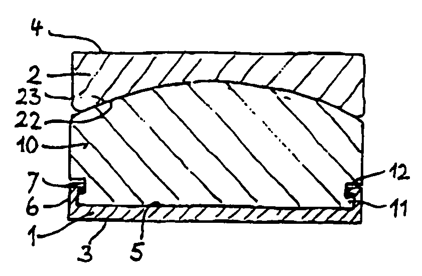
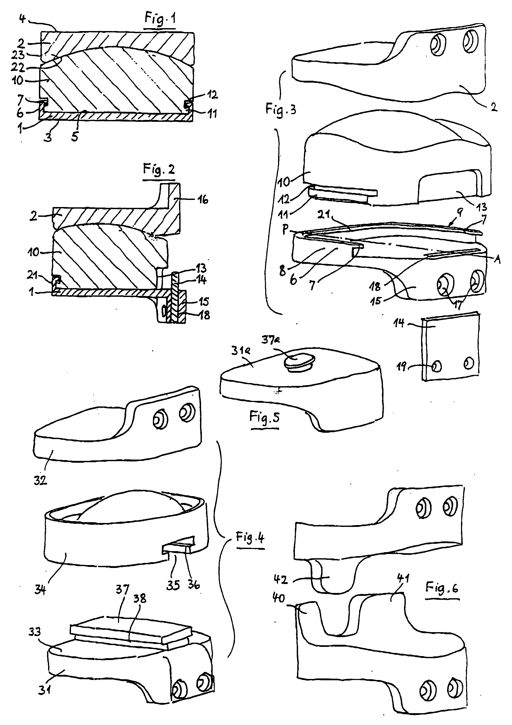
[0021] The lower cover plate 1 and the upper cover plate 2 of the first embodiment have outer surfaces 3 and 4, respectively, which are intended for anchoring to the associated vertebral body. They are preferably plane. However, other substantially flat configurations including suitable surface structures for better anchoring to the bone are also conceivable. The cover plates are preferably made of metal.

[0022] The lower cover plate 1 has a plane upper surface 5 facing toward the upper cover plate 2 and enclosed on three sides by a collar 6 which, above an inner undercut, forms an inwardly projecting ridge 7. The lower cover plate 1 is of approximately rectangular shape in plan view. In the area of its sides 8, 9, the branches of the collar 6 located there extend parallel to one another and rectilinearly.

[0023] The upper surface 5 and the collar 6 of the lower cover plate form a seat for the prosthesis core 10, which is made of a material with good sliding properties, for example ...


PUM


Abstract

An intervertebral prosthesis system, in particular for the cervical spine, includes at least two types of prothesis. The type of prothesis includes a first cover plate that is configured to be connected to a first vertebral body, a second cover plate that is configured to be connected to a second vertebral body, and a prothesis core which is held by a seat on the first cover plate and forms an articulation with the second cover plate. The core of the first type of prosthesis is movable in the anterior-posterior direction relative to the first cover plate. Mobility can also be provided in the lateral direction and rotational direction. The second type of prosthesis of the system may be the same as the first type of prosthesis or may be different, but in all examples of the second type of prosthesis the core is not movable relative to either cover plate.

Description

REFERENCE TO RELATED APPLICATION [0001] This application is a division of Ser. No. 10 / 356,711, filed Feb. 3, 2003, now abandoned, the disclosure of which is incorporated by reference.FIELD AND BACKGROUND OF THE INVENTION [0002] Intervertebral prostheses are used for replacing the intervertebral disk. They comprise two cover plates, whose outer surfaces are designed for connection to adjacent vertebral bodies, and an articulation device enclosed by the cover plates. In a known prosthesis (EP-B 471 821), the upper cover plate forms a concavely spherical articulation surface on its inner side, which cooperates with the convexly spherical top surface of a prosthesis core of polyethylene in order to form an articulation. The core has a flat underside and a cylindrical edge which are received with matching fit in a seat which is formed on the inside by the lower cover plate. [0003] In order to permit easy flexion movement, it would be useful to choose a small radius of curvature of the ar...

Claims


Application Information

Patent Timeline
Patent Type & Authority Applications(United States)
IPC IPC(8): A61F2/44A61F2/00A61F2/30
CPCA61F2/4425A61F2002/30387A61F2002/30392A61F2002/30397A61F2002/304A61F2002/30517A61F2002/30578A61F2002/30616A61F2002/30649A61F2002/443A61F2220/0025A61F2310/00011
Inventor KELLER, ARNOLDMCAFEE, PAUL
Owner CERVITECH INC
Why Eureka
Try Eureka