

Goggle lens interchange system
- Summary
- Abstract
- Description
- Claims
- Application Information
AI Technical Summary
Benefits of technology
Problems solved by technology
Method used
Image

Examples
first embodiment
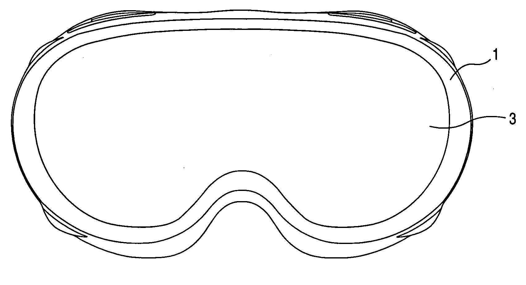
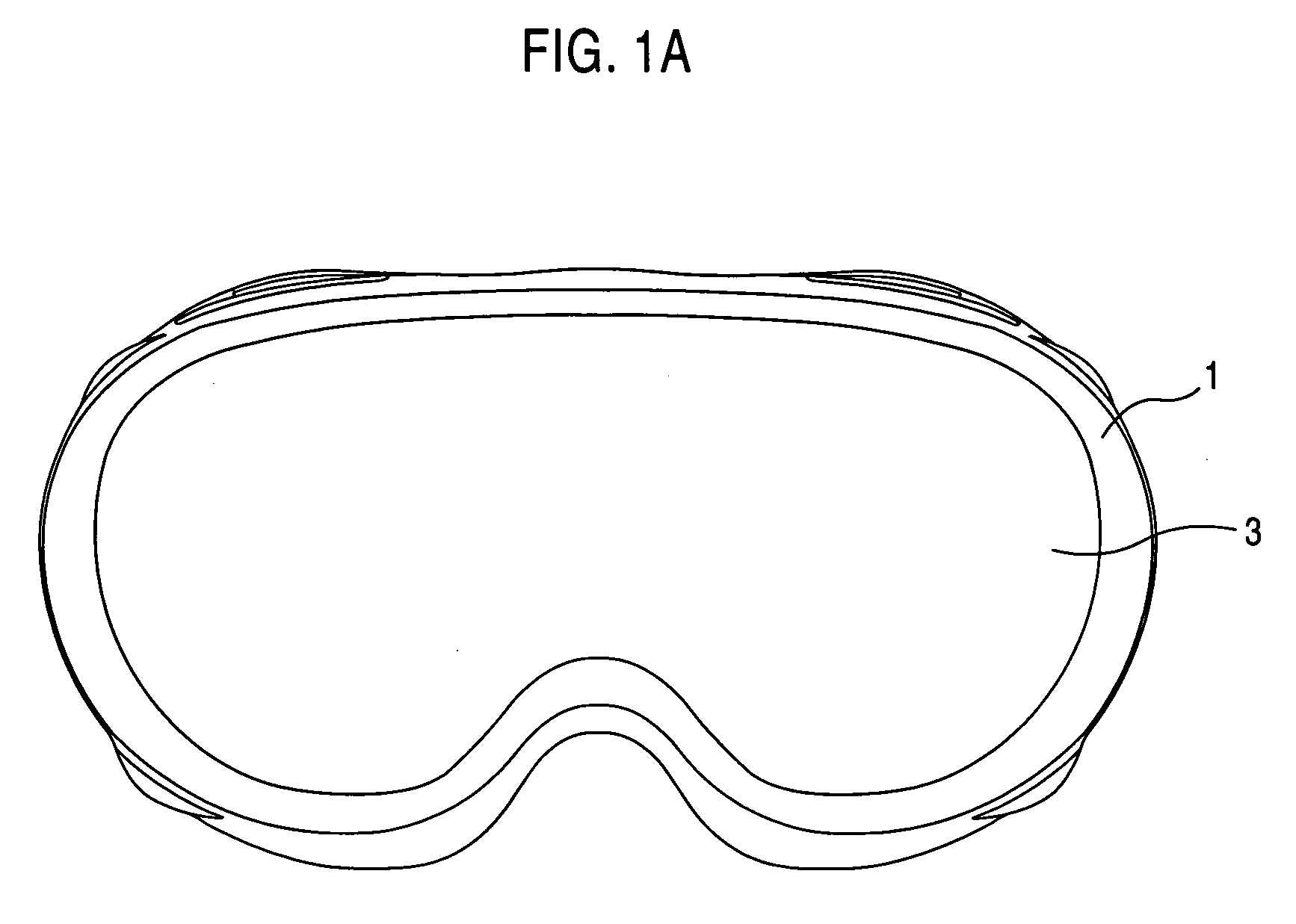
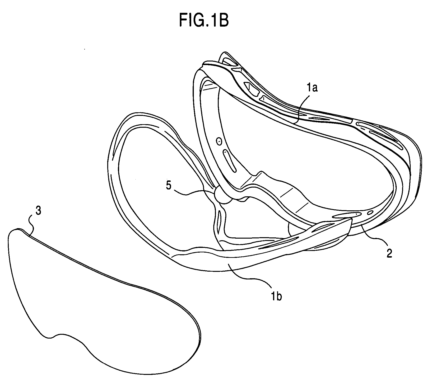
[0040]FIGS. 1A and 1B illustrate a goggle lens interchange system according to the present invention.
[0041] As shown in FIGS. 1A and 1B, the goggle lens interchange system of the first embodiment of the present invention includes a frame 1 having a ledge 2 onto which a lens 3 is removably placed. The frame 1 opens, as shown in FIG. 1B, providing a rear portion 1a and a front portion 1b connected by a hinging mechanism 5. The hinging mechanism 5 allows the front and rear frame portions 1b, 1a to be disengaged on at least three sides thereof to allow access to the ledge 2 for easy lens replacement.
[0042] The lens of the first embodiment may include an outer lens separated from an inner lens by at least a gasket. In addition, there may be an air space between the outer and inner lenses. An example of such a lens is illustrated in FIG. 4A.
[0043] An exemplary method of operating the goggle lens interchange system of FIGS. 1A and 1B will now be described with respect to FIGS. 1C-1F.
[00...
second embodiment
[0055]FIG. 5C illustrates a case where there are two latches 40B and two hinging mechanisms 50B disposed at right and left sides of a rear goggle frame 10B. In the variation of the second embodiment shown in FIG. 5C, the hinging mechanisms 50B are positioned at a center, in the vertical direction, of the latches 40B and sides of the rear goggle frame 10B. In this case, the latches 40B open by swinging away from each other in an outward direction, thereby revealing the ledge 2.
[0056] In addition, in the present invention, a hinging mechanism may be disposed at any portion or portions of a latch, a pair of latches, or a plurality of latches, regardless of number, or placement, of the latch(es).
[0057] The goggle lens interchange system of the second embodiment, and variation thereof, may further include strap holder parts (not shown), which cover the latch or latches. In this case, by wearing the goggles, the latch(es) may be restrained from opening.
[0058]FIGS. 3A-3D illustrate a met...
third embodiment
[0063]FIG. 4A illustrates a top perspective view of a goggle lens interchange system according to the present invention.
[0064] As shown in FIG. 4A, a lens 3′, having an outer lens 3a and an inner lens 3b and an air space therebetween, is positioned on a molded ledge 6 of a rear goggle frame 10A, on top of foam 11 and a compressible gasket 12. A front f part of a goggle frame 10B is provided in such a manner as to be able to be in at least an open position, illustrated as 10D, or a closed position, illustrated as 10C. Movement of the front part 10B is provided for by a hinging mechanism 50, which also serves to connect the front part 10B to the rear goggle frame 10A. The front part in the closed position 10C compresses the foam 11 and compressible gasket 12, forming a seal between the lens 3″ and the molded ledge 6 of the rear goggle frame 10A. The front part in the closed position 10C may lock the lens 3″ in place by a snap, undercut, cam, or any other suitable locking mechanism. Fo...
PUM
| Property | Measurement | Unit |
|---|---|---|
| Fraction | aaaaa | aaaaa |
| Compressibility | aaaaa | aaaaa |
Abstract
Description
Claims
Application Information