
Collision detection in a non-dominant bit radio network communication system

a radio network communication system and collision detection technology, applied in the network field, can solve the problems of waste unnecessary complexity, poor use of the available bandwidth of the communication medium,

Inactive Publication Date: 2006-08-31
CLIPSAL INTEGRATED SYST
View PDF17 Cites 60 Cited by
  • Summary
  • Abstract
  • Description
  • Claims
  • Application Information

AI Technical Summary

Benefits of technology

"The present invention provides a data frame for a radio frequency network that includes coded data to avoid collisions between transmissions. The data frame is transmitted from a first device and received by a second device. The second device detects the coded data and recognizes it as indicating a collision. The invention also provides a method for detecting a collision between two transmissions and a system for repeating data between devices. The technical effects of the invention include improved data transmission reliability and reduced collisions between transmissions."

Problems solved by technology

This has the drawback that the transmitting device must know exactly the number of receiving devices within the network, and how to contact each of them.
The repetitive transmission of the same data to many recipients wastes the available bandwidth of the communication medium.
This approach allows the creation of a shared network variable, at the expense of unnecessary complexity and poor use of the available bandwidth of the communication medium.
This renders the data transfer unreliable, and the transmitter will not be able to determine whether all of the receiving devices have successfully received the data.
Unreliable transfer of data means that a shared network variable cannot be created.
The situation is compounded when two or more devices are out of communications range of each other.
Communications, and synchronising communications is made more complicated when some devices are outside the maximum range and therefore cannot communicate with each other.
The creation of a shared network variable is also impeded by the occurrence of collisions between transmissions from various devices.
Collisions adversely affect the successful transmission of data throughout the network.
This approach significantly reduces the likelihood of collisions however, is not fail safe and is not necessarily appropriate when multiple networks are used in which devices in different networks may use the same address.

Method used


Image

  • Collision detection in a non-dominant bit radio network communication system
  • Collision detection in a non-dominant bit radio network communication system
  • Collision detection in a non-dominant bit radio network communication system

Examples


Embodiment Construction

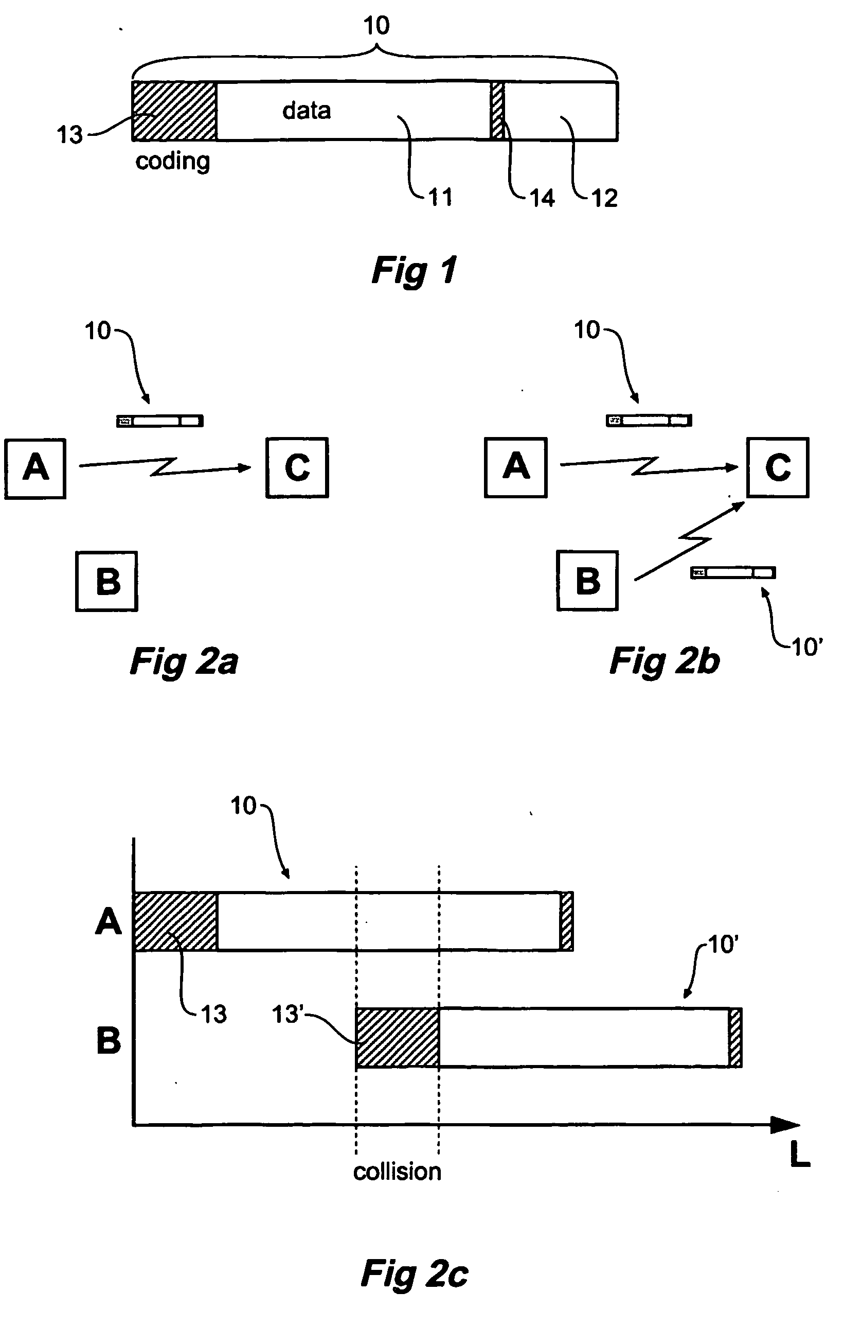
[0049] According to an aspect of the present invention, any collisions that occur, will be detected through the use of coding of data frames transmitted by devices within the network.

[0050] There are two types of collisions that can occur. The first is between two devices, which are in range of each other, that for some reason started transmitting data at the same time. In spite of various avoidance method techniques traditionally used, such as monitoring the medium before transmission and staggering the subsequent transmission of data by devices in accordance with each devices' unit address, a collision may still occur. In this case, the data transmissions will overlap each other in time.

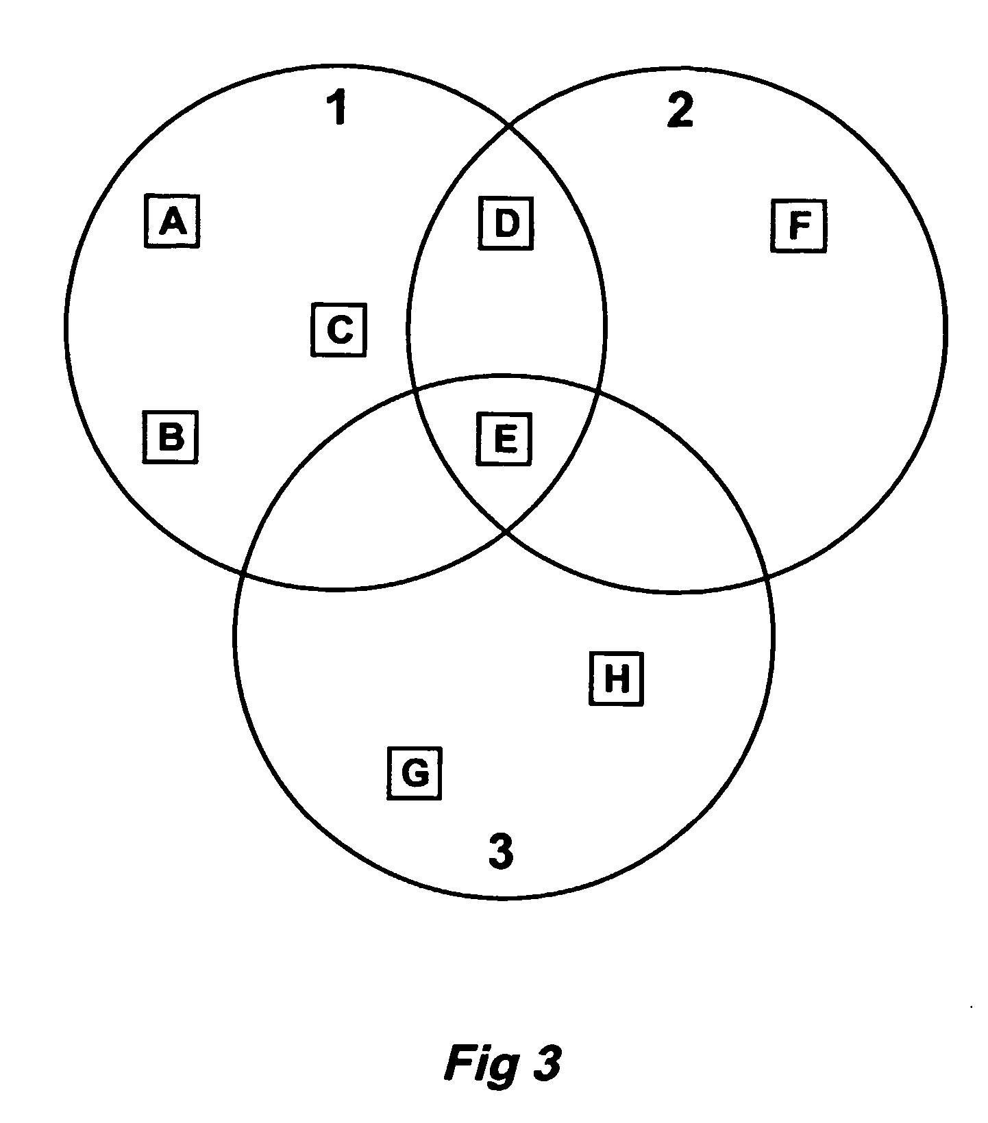
[0051] The other type of collision, and one that is more likely to occur, is in the case where a device needs to transmit data to other devices distributed over several separate networks. Across two of these networks for example, some devices will be close to each other (even though in different ...


PUM


Abstract

A communications system and protocol for use in a non-dominant bit radio network. The radio network includes transceivers which communicate with other transceivers to allow network variables to be shared by all transceivers. The protocol allows the network to handle collisions between competing transmissions from different transceivers. The protocol also handles communications between transceivers that are out of transmitting range of each other.

Description

TECHNICAL FIELD [0001] This invention relates to a network of devices that communicate with each other via radio frequency. BACKGROUND OF THE INVENTION [0002] A network of devices can be created by arranging a group of devices which communicate with each other via radio frequency (RF) means to transmit data between the devices. Provided that each of the devices is within the range of the maximum communications range of each device, each device can effectively communicate with each other device in the network. [0003] The present invention may be used in a “point to multipoint” system as opposed to a “point to point” system in which communications occur between only two devices at a time. In a point to multipoint communication system, communications occur between one device and two or more of the other devices in the network simultaneously. [0004] A reliable “point to multipoint” communication system allows the creation of a shared network variable. This is a variable which is known t...

Claims


Application Information

Patent Timeline
Patent Type & Authority Applications(United States)
IPC IPC(8): H03M7/00H03M13/47H04B7/14H04L12/56
CPCH04L1/0041H04L1/1607H04L2001/0093H04L2001/0097H04W16/14H04W24/00H04W28/04H04W80/00H04L1/16H04W74/08
Inventor QUICK, ASHLEIGH GLENTERRACE, DONALD MURRAY
Owner CLIPSAL INTEGRATED SYST
Learn More