
Apparatus for and method of aligning a spine

a technology of spine alignment and apparatus, which is applied in the field of orthopaedic surgery, can solve the problems of difficult bending of rods on patients during surgery, not without risk to patients, and difficulty in carrying out the procedure properly outside of the patient, and achieves the effect of reducing the risk of patients, and ensuring the patient's safety

Inactive Publication Date: 2006-08-31
SUDDABY LOUBERT
View PDF4 Cites 153 Cited by
  • Summary
  • Abstract
  • Description
  • Claims
  • Application Information

AI Technical Summary

Benefits of technology

"The invention is an apparatus and method for aligning a spine that is easy to implant and has few parts. It uses a segmental rod construct that can be tensioned to form a solid rigid or semi-rigid rod. The interdigitation between component segments is such that they resist all manner of forces. The apparatus includes pins and spacers that can be attached to bones and a means for restricting movement among them. The invention provides improved elements and arrangements that are inexpensive, dependable, and effective in accomplishing intended purposes."

Problems solved by technology

Accommodating the spine and providing appropriate curvature requires bending the rods in two planes, the sagittal and frontal planes, which is complex and difficult to undertake properly outside of the patient.
Bending the rods on the patient during surgery also is difficult and not without risk to the patient.
Spinal osteosynthesis devices typically have a large number of parts.
The number and complexity of parts of these devices increases the costs and failure modes thereof.
This complexity increases surgical implantation time and cost.

Method used


Image

  • Apparatus for and method of aligning a spine
  • Apparatus for and method of aligning a spine
  • Apparatus for and method of aligning a spine

Examples


Embodiment Construction

[0023] The invention is an apparatus for aligning a spine that is easy to implant and configured with few parts, and a method of aligning a spine that promotes reduced device and implantation cost and surgical duration, cost and risk.

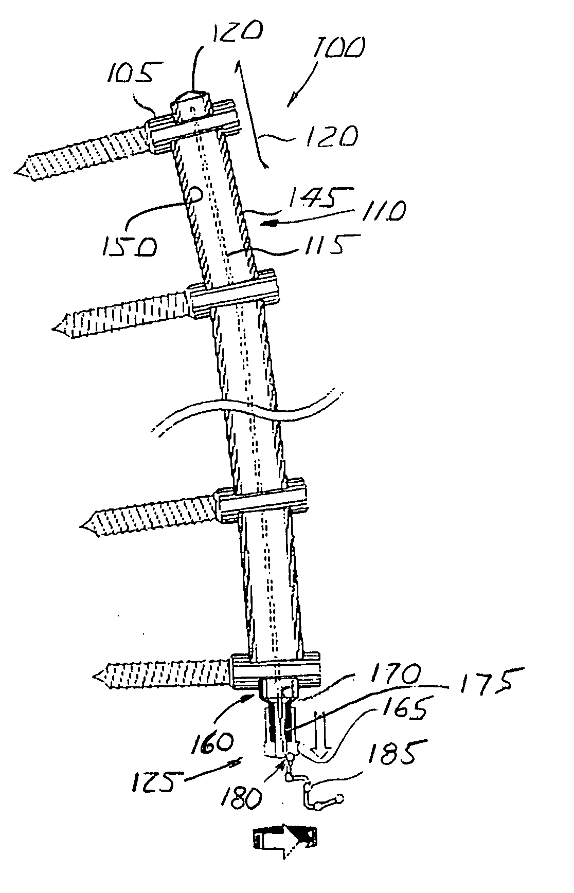
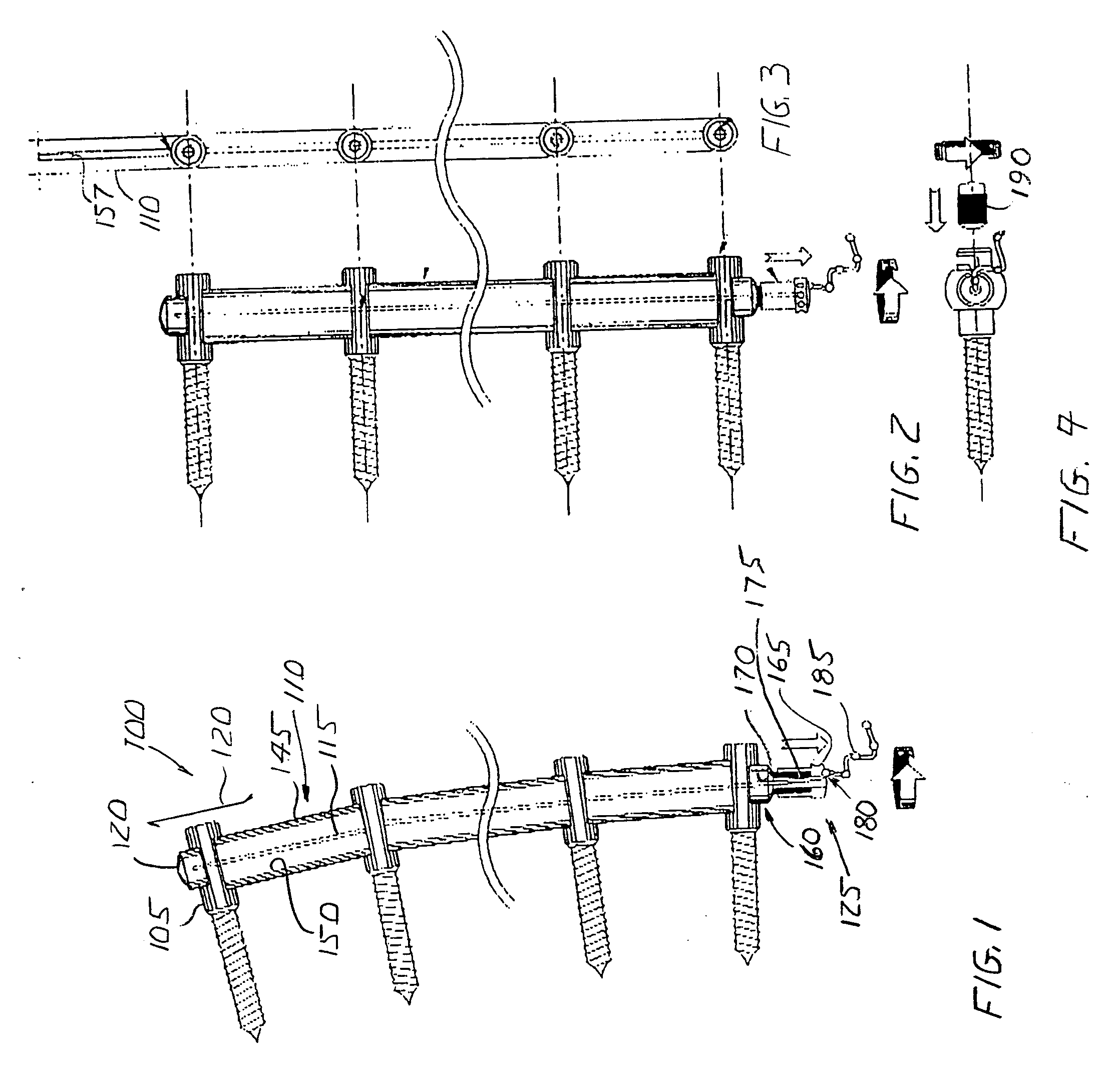
[0024] Referring to FIG. 1, an embodiment of an apparatus 100 configured according to principles of the invention includes a plurality of pins 105 configured to attach to bone, such as a vertebra (not shown). Spacers 110 interpose between pins 105. A cable 115 extends through pins 105 and spacers 110 between a cap 120 and an expansion sleeve 125.

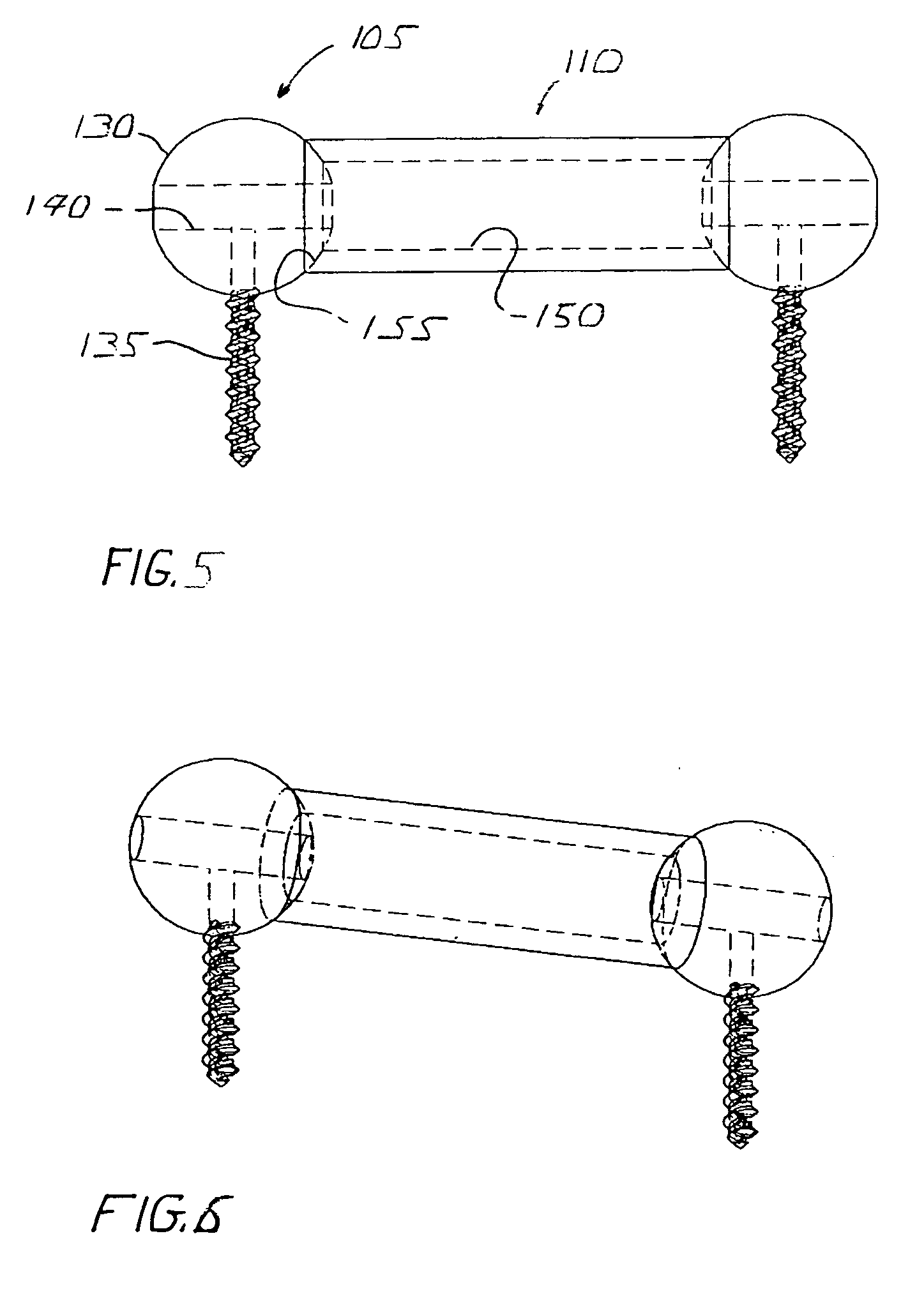
[0025] Referring also to FIGS. 5 and 6, pin 105 has a head 130, a stem 135 and a passage 140 therethrough. Head 130 has a surface that is knurled or otherwise treated for selective frictional engagement with spacer 110, as described below. Head 130 also has a driver socket (not shown) or other means for being driven into or attached to bone, as described below.

[0026] Stem 135 is configured to attach to bone. ...


PUM


Abstract

A plurality of pins attach to bone, such as a vertebra (not shown). Spacers interpose between pins. A cable extends through pins and spacers between a cap and an expansion sleeve. The expansion sleeve increases cable tension to restrict movement among pins and spacers.

Description

BACKGROUND OF THE INVENTION [0001] This invention relates to the field of orthopedic surgery and particularly to the restoration and preservation of spinal alignment. [0002] Spinal osteosynthesis devices typically include rigid rods that are connected to the vertebrae of the spine with a bone anchor. The rods are bent to accommodate or provide curvature appropriate to the anatomy of a spinal segment. The bone anchors often include screws or pedicle hooks. Sometimes adjacent rods are interconnected transversely. [0003] Accommodating the spine and providing appropriate curvature requires bending the rods in two planes, the sagittal and frontal planes, which is complex and difficult to undertake properly outside of the patient. Bending the rods on the patient during surgery also is difficult and not without risk to the patient. [0004] Spinal osteosynthesis devices typically have a large number of parts. The number and complexity of parts of these devices increases the costs and failure...

Claims


Application Information

Patent Timeline
Patent Type & Authority Applications(United States)
IPC IPC(8): A61B17/58A61B17/56
CPCA61B17/7008A61B17/7011
Inventor SUDDABY, LOUBERT
Owner SUDDABY LOUBERT
Learn More