
Sternum closure device having locking member

a technology of sternum and locking member, which is applied in the field of surgical devices, can solve the problems of sternal non-union, steel wires can and do break, and steel wires are difficult to maneuver and place around the sternum, and achieve the effect of convenient access

Inactive Publication Date: 2006-08-31
STEVENS LEONARD
View PDF28 Cites 166 Cited by
  • Summary
  • Abstract
  • Description
  • Claims
  • Application Information

AI Technical Summary

Benefits of technology

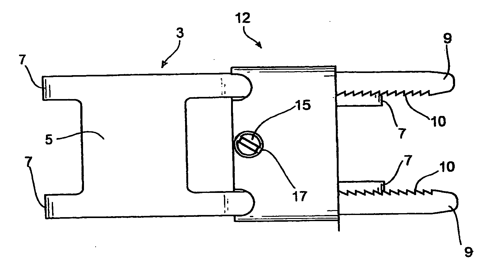
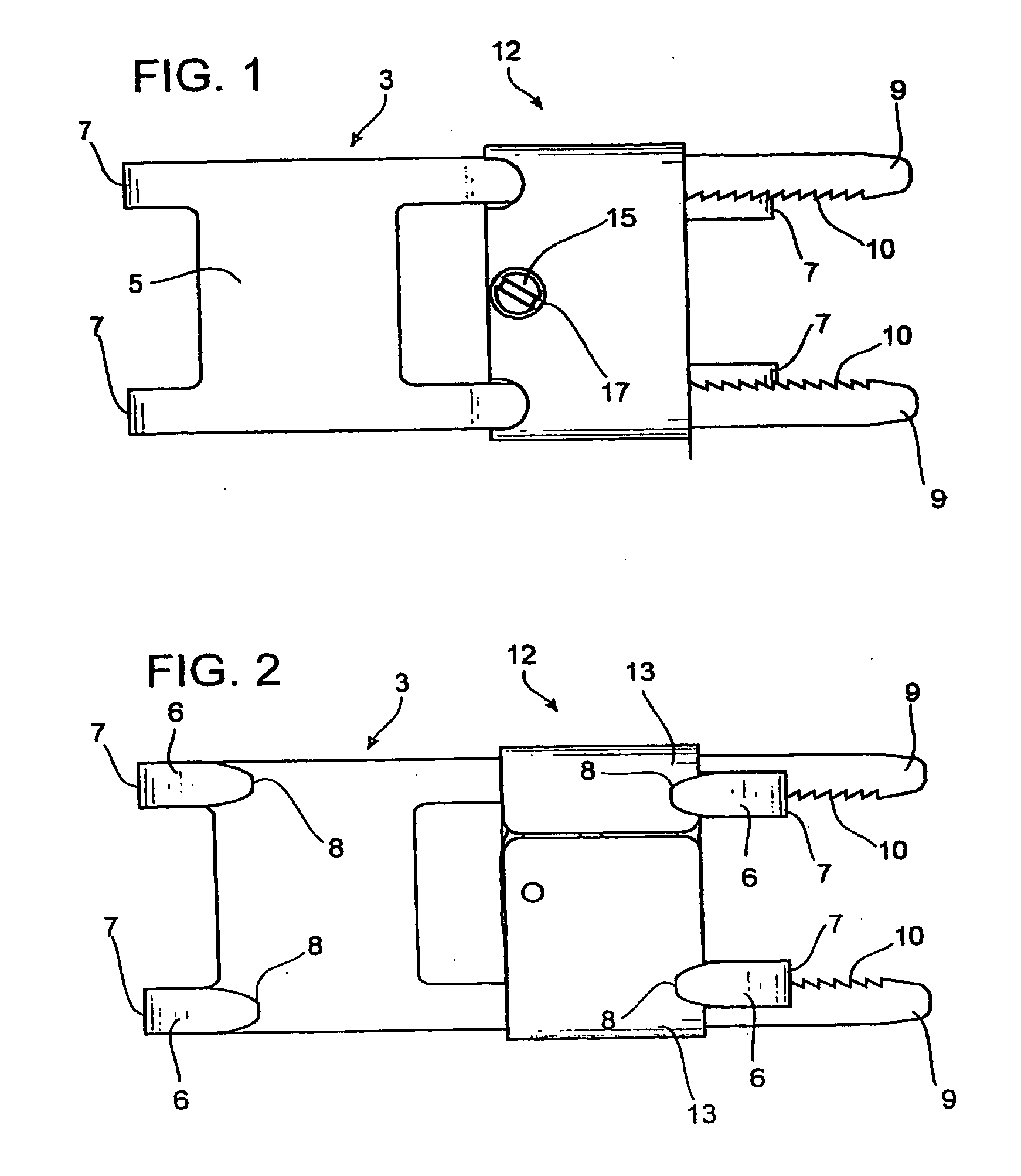
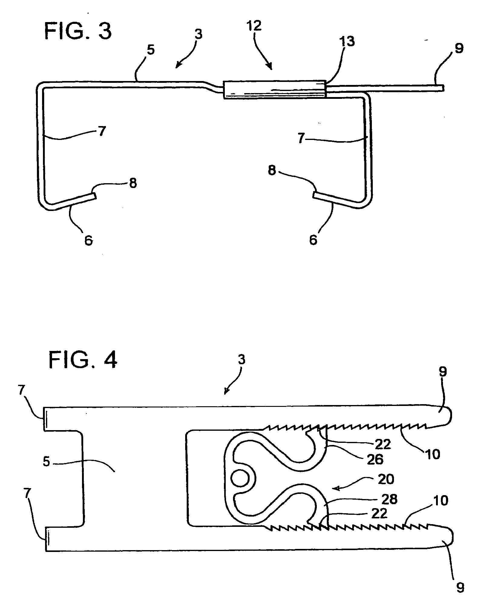
[0007] The present invention provides an improved device and method for re-approximating the sternal halves of a patient's sternum following a median or partial sternotomy, and facilitates ready access to the thoracic cavity during or after a medical procedure advanced the art by overcoming the sternal nonunion problems inherent in prior art devices.

Problems solved by technology

While utilization of steel wires and strap assemblies have been widely accepted for sternum repair, these devices present a number of disadvantages.
Steel wires can and do break, and provide insufficient (non-uniform) clamping force resulting in sternal nonunion.
Steel wires are difficult to maneuver and place around the sternum.
The cut ends of the steel wires are also sharp and can pierce through the surgeon's gloves or fingers.
In addition, the small diameter of the steel wires can cause the wires to migrate into or through the tissue surrounding the sternum region or into the sternal bone itself over time and result in sternal disintegration into small segments.
This can lead to significant patient pain and discomfort in addition to slowing the postoperative recovery and increasing the risk of sternal infection.
Moreover, the strap mechanisms of band assemblies are often relatively structurally complex and are difficult to precisely apply about the sternum.
There are also healing problems associated with the use of steel wires and band assemblies due to improper forces exerted by these devices which can cause unwanted bone movements leading to raking and rubbing of surrounding tissue or bone.

Method used


Image

  • Sternum closure device having locking member
  • Sternum closure device having locking member
  • Sternum closure device having locking member

Examples


Embodiment Construction

[0021] While the making and using of various embodiments of the present invention are discussed in detail below, it should be appreciated that the present invention provides for inventive concepts capable of being embodied in a variety of specific contexts. The specific embodiments discussed herein are merely illustrative of specific manners in which to make and use the invention and are not to be interpreted as limiting the scope of the present invention.

[0022] While the invention has been described with a certain degree of particularity, it is clear that many changes may be made in the details of construction and the arrangement of components without departing from the spirit and scope of this disclosure. It is understood that the invention is not limited to the embodiments set forth herein for purposes of exemplification, but is to be limited only by the scope of the attached claim or claims, including the full range of equivalency to which each element thereof is entitled.

[002...


PUM


Abstract

A sternal closure device including impermanently joined sliding and receiving attachment structures which are adapted for intercostal positioning between at least two corresponding rib pairs and substantially surrounding a patient's sternum with each structure having a cross member, a plurality of integrated legs and foot members, a plurality of sternum engagement surfaces, and an end portion. The receiving structure further incorporates a generally bow-shaped locking member with angularly disposed teeth-like structures positioned to receive and position a plurality of receiving structure projection members when inserted therein. The locking member further serves as a stabilizing structure with stabilization facilitated via an easily removed single screw like structure markedly facilitates quick release. The projection members further embody complimenting positioned teeth-like structures providing for racheting, unidirectional entry and positioning within the receiving attachment structure.

Description

REFERENCE TO RELATED APPLICATIONS [0001] This application is a continuation-in-part of U.S. patent application Ser. No. 10 / 699,208 filed Oct. 31, 2003.TECHNICAL FIELD OF THE INVENTION [0002] This invention relates generally to surgical devices. More specifically, the present invention relates to improved sternum clamping devices and methods to reapproximate a patient's sternum following a partial median sternotomy. BACKGROUND OF THE INVENTION [0003] A partial or median sternotomy is a procedure by which a saw or other appropriate cutting instrument is used to make a midline, longitudinal incision along a portion or the entire axial length of the patient's sternum, allowing two opposing sternal halves to be separated laterally. A large opening into the thoracic cavity is thus created, through which a surgeon may directly visualize and operate upon the heart and other thoracic organs or tissues. Following such a procedure, the two severed sternal halves must be reapproximated. [0004] ...

Claims


Application Information

Patent Timeline
Patent Type & Authority Applications(United States)
IPC IPC(8): A61F2/30A61B17/80A61B17/82A61B17/86
CPCA61B17/8004A61B17/8076A61B17/823Y10T24/44624Y10T24/44615Y10T24/44607A61B2017/8655A61B17/8009
Inventor STEVENS, LEONARD
Owner STEVENS LEONARD
Learn More