Picture Frame Hardware Mounting Aid

a technology for mounting aids and picture frames, which is applied in the direction of picture frames, measurement devices, instruments, etc., can solve the problems of multiple unwanted holes in the wall, difficult to determine the precise location of installing nail or picture hooks, and the process of hanging pictures on the wall can be exceptionally frustrating, etc., to achieve convenient promotion, simple use, and cost-effective manufacturing

Inactive Publication Date: 2006-09-07
GROEPPER WILLIAM RYAN
View PDF36 Cites 21 Cited by
  • Summary
  • Abstract
  • Description
  • Claims
  • Application Information

AI Technical Summary

Benefits of technology

[0021] Another object is to provide a device for marking the optimal placement of a picture hanger that can also be used as a system when installing an object with a wire or cord hanger by tensioning said cord to simulate hanging tension and enable locating the precise point on the wall where a fastener should be installed.
[0022] Another object is to provide a device for marking the optimal placement of a picture hanger that is cost effective to manufacture and is conveniently sized for promotion within a retail store environment.
[0023] Another object is to provide a device for marking the optimal placement of a picture hanger that is intuitive and simple to use.

Problems solved by technology

The process of hanging a picture on a wall can be exceptionally frustrating.
As the back of the object is out of sight when placement of the picture on the wall is considered, it is therefore very difficult to determine the precise location to install a nail or picture hook such that the picture is suspended in the desired location.
Thus, hanging a picture in the desired location often results in a trial-and-error process that produces multiple unwanted holes in the wall until happening on the correct position, or simply settling for a picture position that is “close enough”.
The main problem with conventional picture positioning devices is that no single product provides a system for all types of hanging needs that is simple to use, inexpensive to manufacture, is reusable and allows for intuitive picture placement.
Another problem with conventional picture positioning devices is that they are overly complex and prohibitively expensive to manufacture.
Another problem with conventional picture positioning devices is that they are often unwieldy to operate, and too large to be sold in the typical picture frame section of a retail store.
Many of these devices require the user to support the entire weight of the picture frame from the device as the user attempts to find the desired location, which is an unreasonable expectation for larger frames or for many people.
Other devices may work suitably with a common sawtooth hanger, but would not accurately function with the also common triangle and D-ring hanging hardware.
However, all of these devices have the drawback that they only work with one specific type of picture frame hanging apparatus, most typically a cord-based hanging system.
However, this device has several drawbacks.
Not only can excessive pressure permanently indent canvas material and fine artwork, thereby damaging same, a simple tack mark in a wall is often difficult to locate once the picture and the device have been removed from the wall.
Moreover, the block element for use with sawtooth hangers may not exactly mark the correct location, or even work with all sawtooth hangers as the depth and height of various sawtooth hangers differ.
Further, the sawtooth bracket embodiment show in FIGS. 7-9 is overly complex, and therefore relatively expensive to manufacture.

Method used


Image

  • Picture Frame Hardware Mounting Aid
  • Picture Frame Hardware Mounting Aid
  • Picture Frame Hardware Mounting Aid

Examples


Embodiment Construction

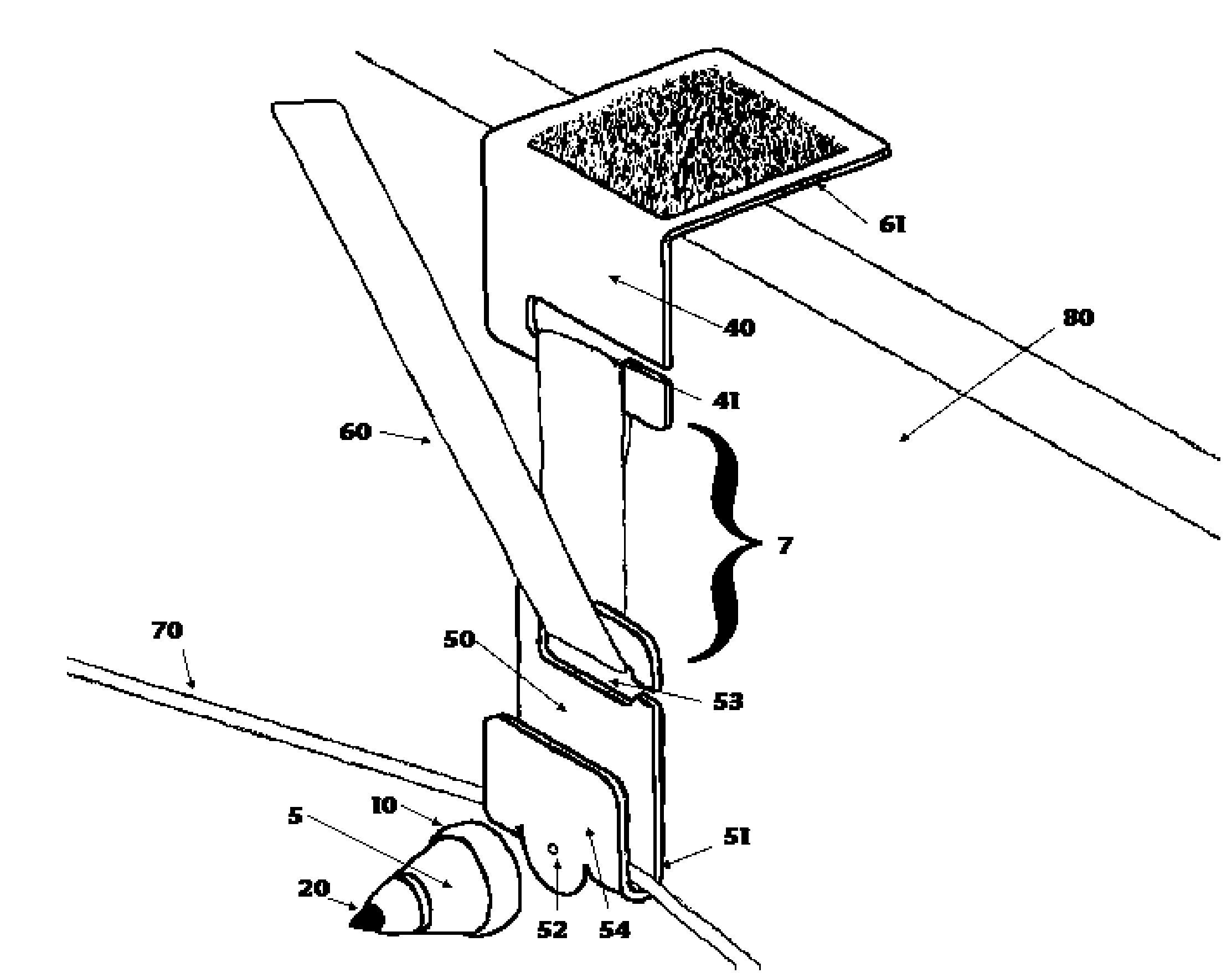
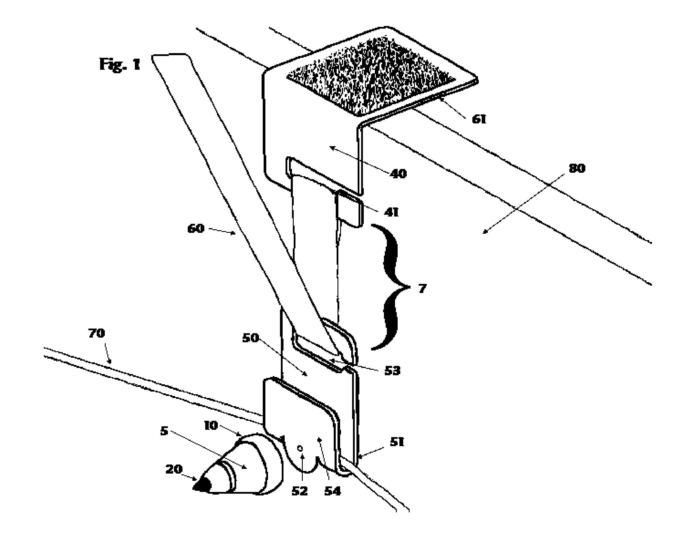
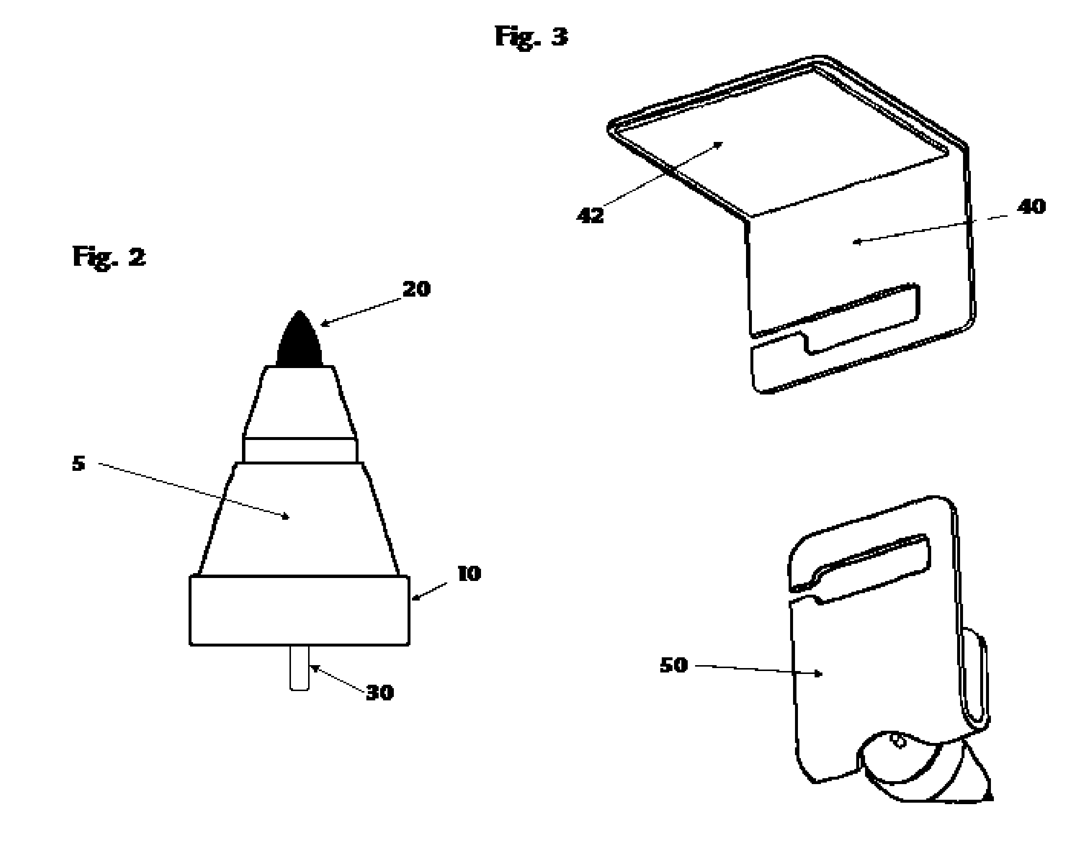
[0035] Turning now to the drawings, in which similar reference characters denote similar elements throughout the several views, the attached figures illustrate a device for marking the optimal placement of a picture hanger. The device comprises a magnetic marking tip 5 for use with smaller picture hanging hardware such as sawtooth hangers, D-rings, triangle hangers and other metal hangers, and a wire adapter 7 device for providing tension on wire hangers 70, as typically found on larger picture frames 80 and mirrors, and to which the marking tip 5 attaches. The marking tip 5 comprises magnet 10 with a coaxially aligned marker 20 and a projecting tip 30 attached to opposite upper and lower sides of the magnet 10. The wire adapter 7 comprises three pieces: an upper member 40 that includes an L-shaped bracket that is frictionally affixed to the top of a picture frame 80 having a cord hanger 70, a lower member 50 having a J-shaped bracket with a hole 52 positioned to optimally receive t...


PUM


Abstract

A device for marking the optimal placement of a picture hanging nail, or the like, on a wall when positioning a picture, or similar object, is disclosed. The inventive device includes a magnetic marking tip for use with smaller picture hanging hardware such as sawtooth hangers, D-rings, triangle hangers and other metal hangers, and a wire adapter device for providing tension on cord based hanger, as typically found on larger picture frames and mirrors. The marking tip attaches to the wire adapter, and comprises a magnet with a coaxially-aligned marker and a projecting tip attached to the opposite sides of the magnet. The wire adapter comprises three pieces: an upper member that is frictionally affixed to the top rear of a picture frame that has a cord hanger, a lower member with a hook to retain the cord hanger, a hole on the hook to receive the marking tip, and a strap for retaining the upper and lower members together and capable of providing tension on the cord in order to position the cord to correspond with a final position when the cord is suspended on a wall-mounted nail or other hardware.

Description

PRIORITY CLAIM [0001] This patent application claims the benefit of U.S. Provisional Application 60 / 645,528, filed on Jan. 20, 2005.FIELD OF THE INVENTION [0002] The present invention relates generally to a picture positioning device, and more specifically to a device for marking the optimal location for installing picture hanging hardware such as a nail, picture hook, or similar device. DESCRIPTION OF THE RELATED ART [0003] The process of hanging a picture on a wall can be exceptionally frustrating. Pictures, artwork, mirrors and similar objects designed to be hung on a wall typically use one of several available means to support the object upon a nail or hook that is fastened to the wall. For example, several prior art means of supporting such an object include a cord which is strung across the back of a frame of the object, hanging hardware specifically designed for the task, such as a sawtooth or triangle hanger, or a D-ring attached to the back of the object. As the back of the...

Claims


Application Information

Patent Timeline
Patent Type & Authority Applications(United States)
IPC IPC(8): G01D21/00
CPCA47G1/205
Inventor GROEPPER, WILLIAM RYAN
Owner GROEPPER WILLIAM RYAN
Why Eureka
Try Eureka