Method for preparing graphics on sheets

a technology of graphics and cutting sheets, applied in metal working apparatus, printing presses, printing presses, etc., can solve the problems of not reaching the highest performance potential of automated cutting systems, requiring manual intervention, time-consuming steps, etc., and achieves the effect of facilitating efficiency improvement and speeding up the effect of determinations involving sensing and processing

Inactive Publication Date: 2006-09-07
MIKKELSEN STEEN +3
View PDF7 Cites 17 Cited by
  • Summary
  • Abstract
  • Description
  • Claims
  • Application Information

AI Technical Summary

Benefits of technology

[0012] Another object of this invention is to provide a method for reducing the time to recognize a specific graphic or sheet of material and identify processing information pertaining to the graphic and / or sheet.
[0049] The inventive apparatus includes: a sheet-receiving surface; a main sensor, preferably a CCD area image sensor; for sensing the subset in the field of view of the main sensor to ascertain the position and orientation of the sheet and to infer approximate positions of the plurality of marks and for sensing the precise positions of the marks; a cutter or other processing device operatively connected to the main sensor and movable about the sheet-receiving surface, the cutter processing the graphic from the sheet of material in response to the precise positions of the registration marks sensed by the main sensor; and a controller for controlling movement of the cutter along the sheet-receiving, the controller including a set of initialization instructions corresponding to (a) predetermined approximate positions of the initial-position / orientation-determining subset on the sheet and (b) the relative positions of the remaining registration marks thereon with respect to the position of the subset. The invention, as already indicated, allows the sensing of the registration marks to occur rapidly and processing to occur precisely despite two-dimensional distortion of the sheet prior to processing.

Problems solved by technology

Achieving greater speed and overall efficiencies in narrow-path-processing is a continuing challenge encountered with such systems.
One source of inefficiency is the manual intervention often required to adjust the initial position and alignment of the sheet on the work surface of the cutting apparatus.
Another source of inefficiency is the time-consuming step which may be required to allow the system to determine the initial position and orientation of the sheet on the work surface.
Another source of inefficiency is the requirement that information pertaining to a specific graphic be created and entered into the processing controller.
Despite the significant advances represented by the i-cut™ system, these advances have not yet achieved the highest levels of performance which potentially can be reached by automated cutting systems.

Method used


Image

  • Method for preparing graphics on sheets
  • Method for preparing graphics on sheets
  • Method for preparing graphics on sheets

Examples


Embodiment Construction

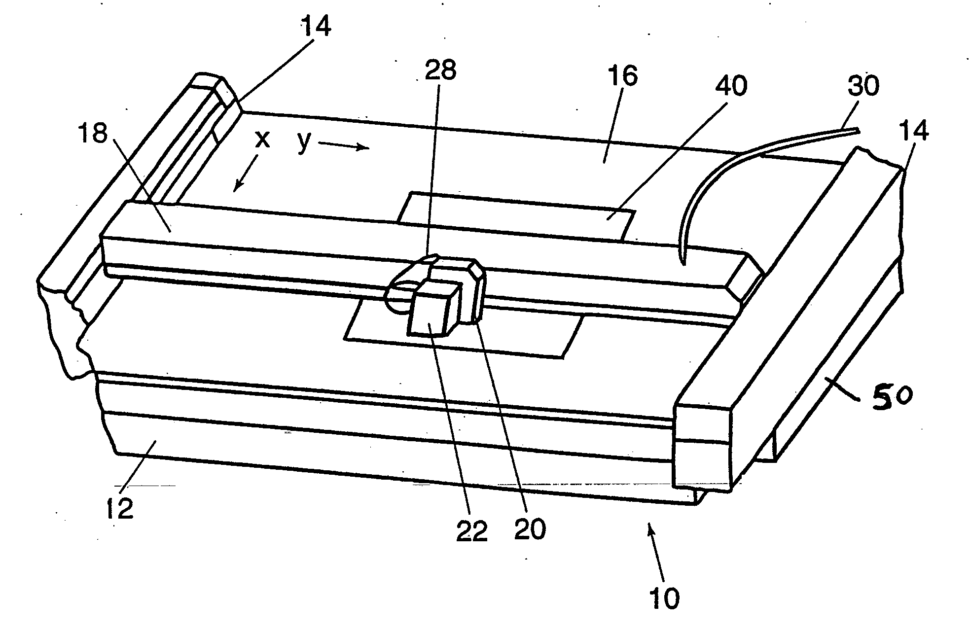
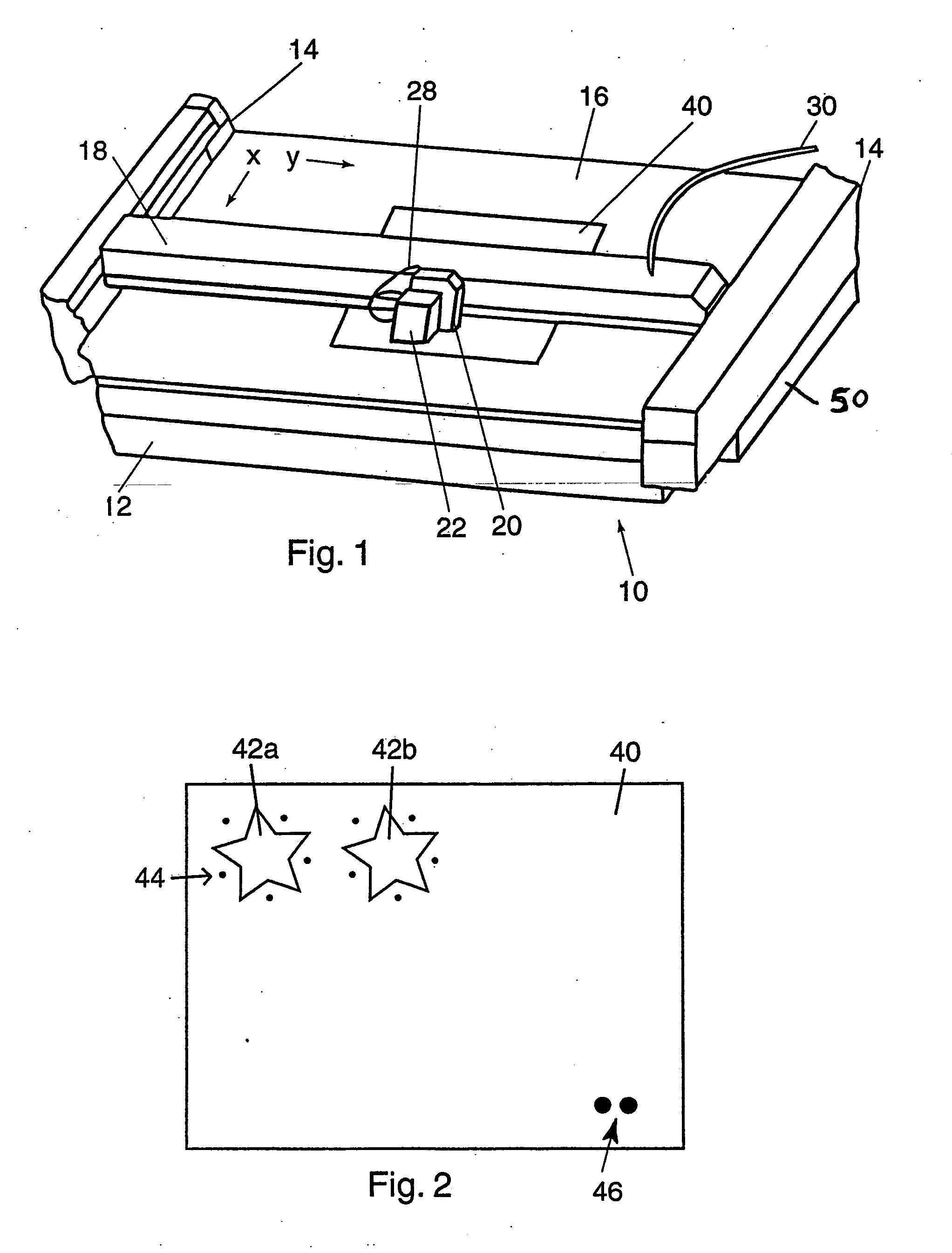
[0075] Referring to FIG. 1, a partially cut away view of a cutting or processing device 10 is shown. Cutting device 10 has a housing 12 which may contain the controller 50 and a sheet-receiving surface 16. Cutting device 10, which is shown with a sheet 40 positioned on sheet-receiving surface 16, is also known as a flatbed plotter or cutter in the art and may be a Zund plotter, manufactured by Zund System Technik HG, or a Wild plotter, to give two examples.

[0076] Cutting device 10 includes two longitudinal guide rails 14 mounted on housing 12 and a transverse member 18 is suspended between longitudinal guide rails 14. Transverse member 18 is driven by a motor (not shown) along guide rails 14. A cutting tool 20 rides on transverse member 18. Cutting tool 20 has a cutting knife (not shown).

[0077] A main sensor 22 is shown attached to cutting tool 20. While sensor or detector 22 is shown attached to cutting tool 10, it is not necessary for it to be attached to it. Main sensor 22 may ...


PUM

PropertyMeasurementUnit
sizeaaaaaaaaaa
sizeaaaaaaaaaa
outer diameteraaaaaaaaaa

Abstract

A method for preparing a graphic on a sheet (40) of material which also includes at least one registration mark (44) at and about the graphic in predetermined positions. The method involves the steps of applying the graphic (42a, 42b) and at least one registration mark on a sheet of material in positions according to layout data, transferring the layout data to a processing controller, placing the sheet of material on a sheet-receiving surface (16), sensing the position of the registration mark on the sheet of material, and utilizing the layout data and the position of the registration mark to precisely narrow-path-process around the graphic on the sheet of material. Certain embodiments use either (a) a subset (46) of marks which is applied on one side of the graphic or (b) certain reference features, such as edges and corners of the sheet and elements of the graphic, to ascertain the position and orientation of the sheet on the apparatus. The invention provides efficient, rapid, automated, and precise processing around the graphic.

Description

RELATED APPLICATION [0001] This is a continuation of patent application Ser. No. 10 / 283,460, filed Oct. 30, 2002, issuing on May 9, 2006 as Patent No. 7,040,204, the contents of which are incorporated herein.FIELD OF THE INVENTION [0002] This invention is related generally to the field of cutting of graphics or the like from sheets for various purposes, and other narrow-path-processing about graphics on sheets. BACKGROUND OF THE INVENTION [0003] The technical field involving the cutting of graphic areas from sheets, or otherwise doing narrow-path-processing about graphics images on sheets, includes, for example, the face-cutting of laminate sheets to form decals. More specifically, a graphic on the face layer of a laminate needs to be cut away from the remainder of the face layer so that the graphic (decal) can subsequently be pulled away from the backing layer of the laminate and be applied elsewhere as intended. Highly accurate face-layer cutting about the graphics is obviously hi...

Claims


Application Information

Patent Timeline
Patent Type & Authority Applications(United States)
IPC IPC(8): B41F1/34B26D5/00B26D7/27B26F1/38
CPCB26D7/27B26F1/3813B26D5/00B26D5/005B26D5/06B26D5/34Y10T83/05Y10T83/0524Y10T83/152Y10T83/178Y10T83/04Y10T83/533Y10T83/543Y10T83/538
Inventor MIKKELSEN, STEENALSTEN, PETERANDERSEN, GEOJANSSON, DAVID G.
Owner MIKKELSEN STEEN
Why Eureka
Try Eureka