Target assignment projectile

a projectile and target technology, applied in the field of projectiles, can solve problems such as risks associated with such a procedur

Active Publication Date: 2006-09-07
MARSUPIAL HLDG
View PDF29 Cites 12 Cited by
  • Summary
  • Abstract
  • Description
  • Claims
  • Application Information

AI Technical Summary

Benefits of technology

[0020] According to another aspect of this disclosure, a projectile includes a communication apparatus including a transmission device for transmitting energy to a remote receiver. A receiving device receives energy from a remote transmitter, and an ordnance portion is positioned forward of the communication apparatus and configured to partially penetrate a target such that at least a portion of the communication apparatus is remotely visible. The projectile is configured to rotate about and travel along a longitudinal axis after launch. One or more interconnections electrically couple a plurality of electronic components internal to the projectile, wherein at least one interconnection is configured to allow a limited amount of relative movement between the plurality of electronic components.

Problems solved by technology

Unfortunately, this activity requires that a person (e.g., a spy, a soldier, or a detective, for example) enter the place that they wish to monitor so that the “bug” can be planted.
Naturally, there are risks associated with such a procedure.
Unfortunately, in order to illuminate a target, a laser must be aimed at and maintained on the target until the missile / bomb strikes the target.

Method used


Image

  • Target assignment projectile
  • Target assignment projectile
  • Target assignment projectile

Examples


Embodiment Construction

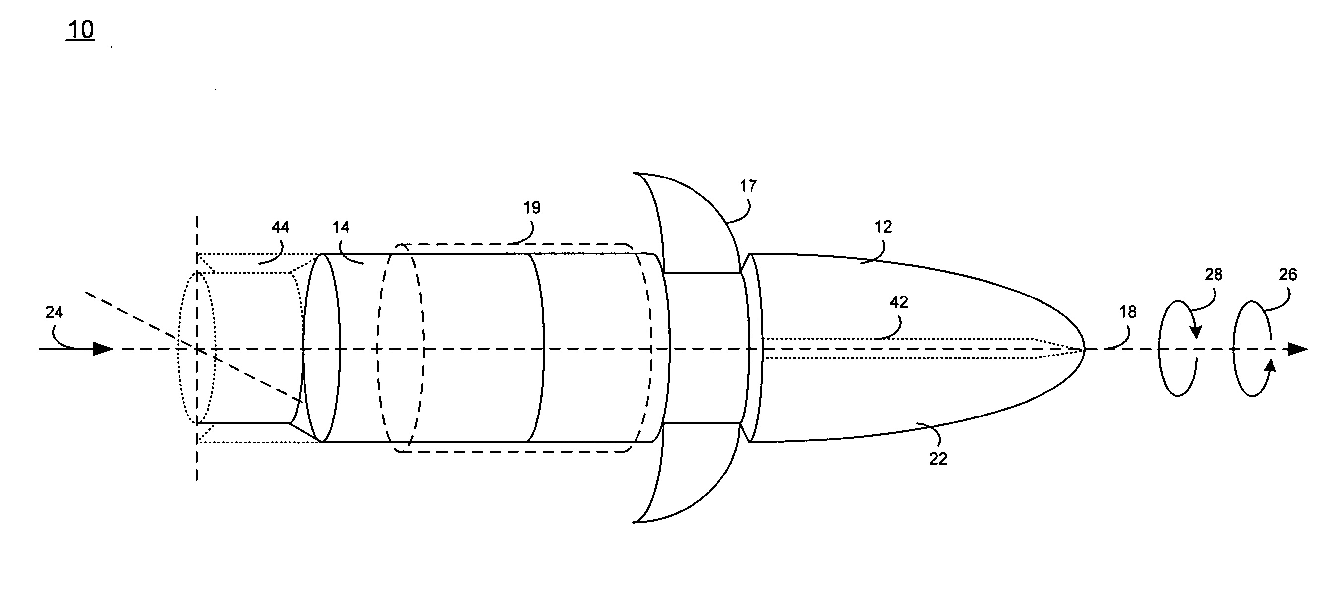
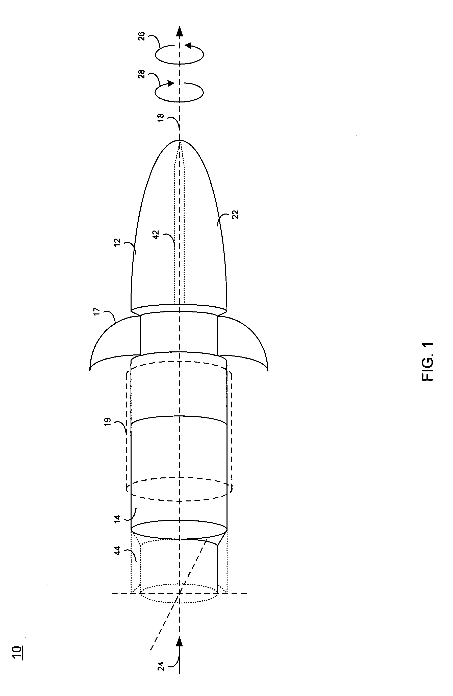
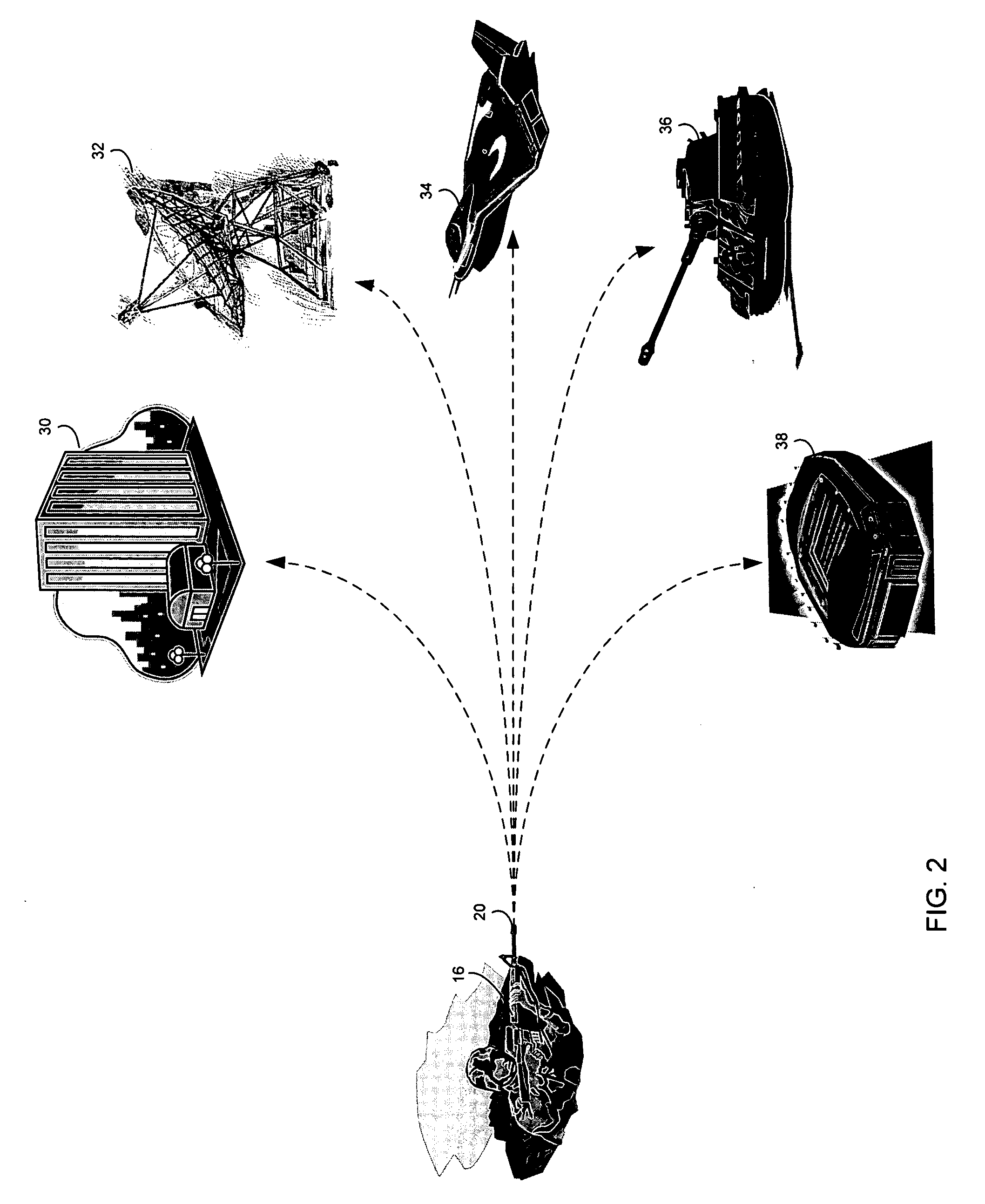
[0029] Referring to FIGS. 1 and 2, there is shown a projectile 10, including an ordnance portion 12 and a communication apparatus 14, that is configured to be launched from a launcher 16 (e.g., a handgun, a rifle, or a cannon, for example). Examples of projectile 10 include a bullet, a rocket propelled grenade, a dart, or an artillery shell, for example. In order to facilitate stable flight, projectile 10 is configured to rotate about its longitudinal axis 18 once launched. Alternative methods for stabilizing the projectile include: deployable fins 17 constructed out of e.g., spring steel or titanium that extend after leaving the launching barrel; or a Sabot 19 that encases the projectile and provides aerodynamic control surfaces. Typically, the rotation of projectile 10 about longitudinal axis 18 is achieved by incorporating rifling (i.e., one or more spiral grooves; not shown) into the inner surface of the barrel 20 from which projectile 10 is launched, which are engaged by the ou...


PUM


Abstract

A projectile includes an ordnance portion configured to impact a target and a communication apparatus positioned rearward of the ordnance portion. The projectile is configured to rotate about and travel along a longitudinal axis after launch.

Description

RELATED APPLICATIONS [0001] This application is a Conversion Application of and claims priority to U.S. Provisional Patent Application 60 / ______ , filed Sep. 27, 2003, and entitled “Target Assignment Projectile”.TECHNICAL FIELD [0002] This disclosure generally relates to projectiles and, more particularly, to communicating projectiles. BACKGROUND [0003] It is often desirable to remotely monitor people and places. This monitoring activity was traditionally accomplished by planting a “bug”, such that the “bug” is a covert microphone or video camera, for example. Unfortunately, this activity requires that a person (e.g., a spy, a soldier, or a detective, for example) enter the place that they wish to monitor so that the “bug” can be planted. Naturally, there are risks associated with such a procedure. [0004] Further, the use of smart munitions (e.g., laser-guided missiles and bombs, for example) have greatly increased the accuracy of munitions. Typically, the target is illuminated (i.e...

Claims


Application Information

Patent Timeline
Patent Type & Authority Applications(United States)
IPC IPC(8): F42B14/06
CPCF42B12/365F42B12/382
Inventor PARKER, WILLIAM P.BIBBY, THOMAS F.A.
Owner MARSUPIAL HLDG
Why Eureka
Try Eureka