Propulsion device

a technology of propellers and propellers, which is applied in the direction of propellers, transportation and packaging, aircraft navigation control, etc., can solve the problems of difficult control, intrinsic danger, and extremely short flight time, and achieve the effect of safe us

Inactive Publication Date: 2006-09-07
MARTIN AIRCRAFT CO LTD
View PDF29 Cites 34 Cited by
  • Summary
  • Abstract
  • Description
  • Claims
  • Application Information

AI Technical Summary

Benefits of technology

[0010] An object of the present invention is a personal flight device which overcomes the disadvantages of the prior art devices described above, and which provides a lightweight yet powerful personal flight device which is comparatively safe to use.

Problems solved by technology

Personal flight devices were developed in the 1960s and 1970s, but were essentially rocket based devices (jet belts) which gave extremely short flight times (typically about 26 seconds) and were difficult to control.
Further, these devices were fuelled by rocket fuel which is intrinsically dangerous.
However, in this design the two fans are contra-rotating and thus have to be driven via a gearbox using a relatively complex rigid transmission system; this adds considerable weight to the device.
Single propeller / fan devices have the drawback that the propeller / fan has to be extremely large to provide adequate lift, and to balance the devices the pilot generally has the propeller / fan above or below him, which is far from ideal from a safety point of view.
A further drawback is that the thrust from a single propeller / fan has to be split in some way to give steering and this tends to result in high frictional losses in the steering tubes or ducts.

Method used


Image

  • Propulsion device
  • Propulsion device
  • Propulsion device

Examples


Embodiment Construction

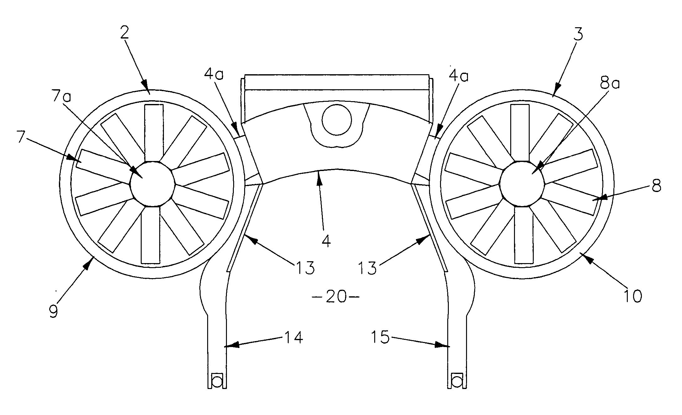
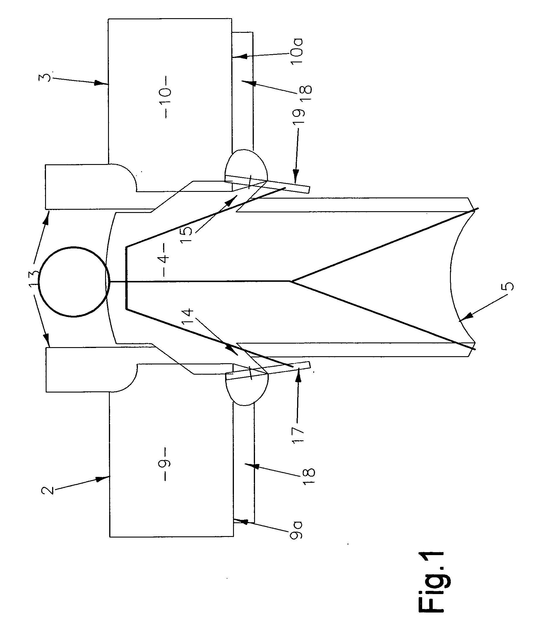
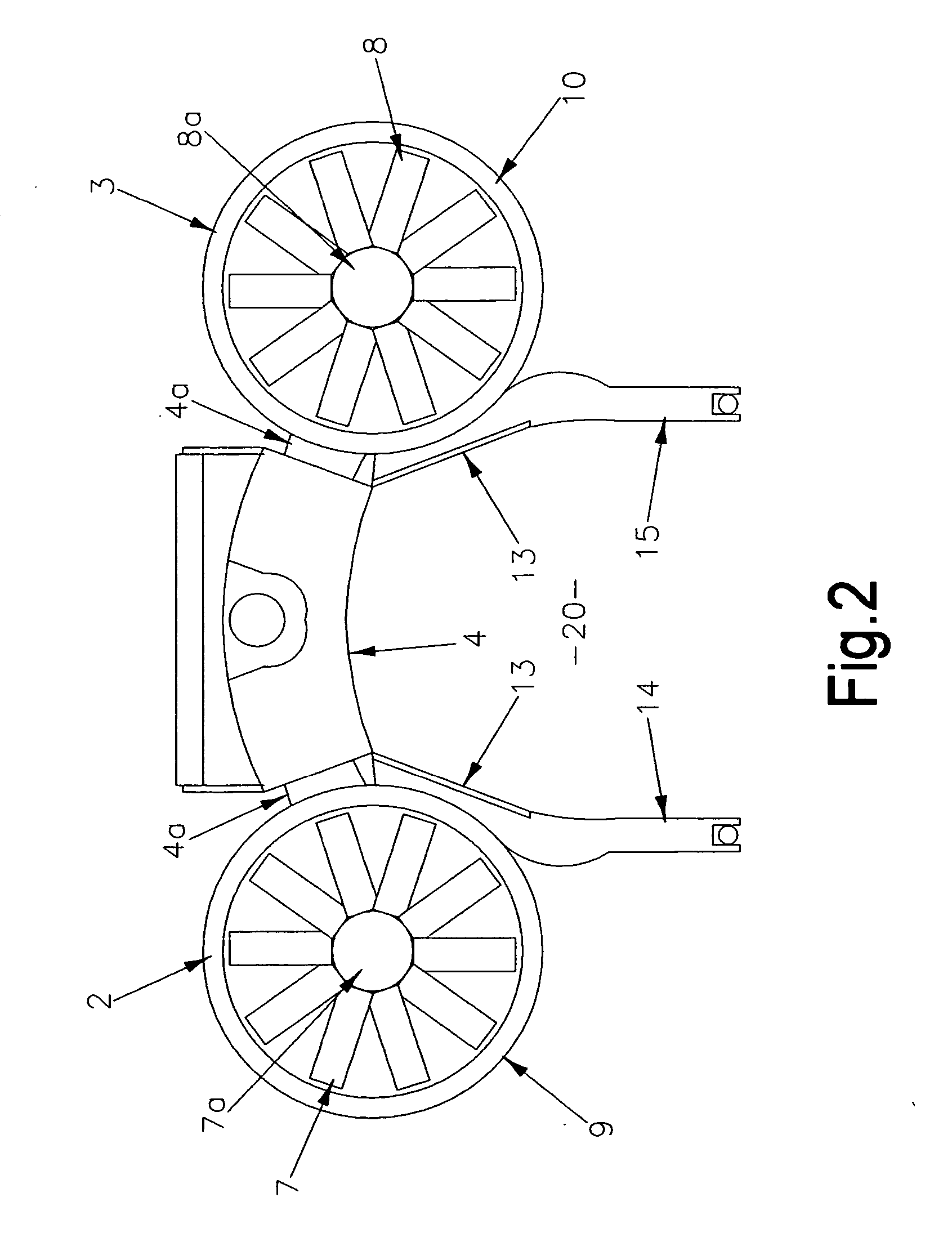
[0033] Referring to the drawings, a personal flight device 1 includes a pair of ducted fans 2,3 which are supported and spaced apart by a central housing 4, which also supports an engine 6 and a fuel tank (not visible).

[0034] The ducted fans 2,3 are of known design and consist of a central multi-blade fan 7,8 mounted on, and rotatable with, a hub 7a,8a, inside a concentric cylindrical duct 9, 10. The ducts 9,10 are rigidly mounted on the housing 4 by mounting brackets 4a (visible in FIG. 2 only) and are oriented such that in the “at rest” position shown in FIGS. 1 and 3, (i.e. when the device is resting on the ground) the axis of rotation of each fan is substantially vertical. The ends of the ducts 9,10 are depicted as open, but may in fact be covered by a protective grill or mesh.

[0035] The fans 7,8 are driven from the engine 6 by a drive means in the form of a pair of toothed drive belts 11a,11b to the corresponding hub 7a,8a. The toothed belt drive is shown (diagrammatically) i...


PUM


Abstract

A personal flight device which consists of a housing securable to a pilot, at least one pair of fans, and at least one engine mounted on the housing for driving the fans; one fan of the pair is mounted to one side of the housing and the other fan of the pair is mounted to the other side of the housing; in use, both fans rotate in the same direction for producing thrust.

Description

CROSS-REFERENCE TO RELATED APPLICATION [0001] This application is based upon and claims priority on New Zealand Patent Application No. 538630, filed on Mar. 4, 2005. FIELD OF THE INVENTION [0002] The present invention relates to a vertical take-off and landing personal flight device, i.e. a device which can be secured to the pilot rather like a jet belt, and which gives the pilot controllable powered flight. BACKGROUND OF THE INVENTION [0003] Personal flight devices were developed in the 1960s and 1970s, but were essentially rocket based devices (jet belts) which gave extremely short flight times (typically about 26 seconds) and were difficult to control. Further, these devices were fuelled by rocket fuel which is intrinsically dangerous. [0004] In a related type of device fuel is fed to a catalyst bed to produce hot gas which is distributed between two spaced counter-rotating turbines to generate -vertical thrust from the turbine exhausts. The device is steered by shrouds or deflec...

Claims


Application Information

Patent Timeline
Patent Type & Authority Applications(United States)
IPC IPC(8): B64C39/02
CPCB64C15/00B64C27/20B64C39/026B64D35/04
Inventor MARTIN, GLENN NEIL
Owner MARTIN AIRCRAFT CO LTD
Why Eureka
Try Eureka