
Electromagnetic actuator

Active Publication Date: 2006-09-07
PRATT & WHITNEY CANADA CORP
View PDF27 Cites 17 Cited by
  • Summary
  • Abstract
  • Description
  • Claims
  • Application Information

AI Technical Summary

Benefits of technology

[0008] The electromagnetic actuator of the present invention advantageously has a very high force capacity in addition to a very cont

Problems solved by technology

Such translators can move the armature in nanometer increments, and can exert very large forces, because they rely on the stiffness of an expanding or contracting material.
The performance efficiency of the actuators disclosed in those prior art documents is limited due to the limitation of the structures thereof.

Method used


Image

  • Electromagnetic actuator
  • Electromagnetic actuator
  • Electromagnetic actuator

Examples


Embodiment Construction

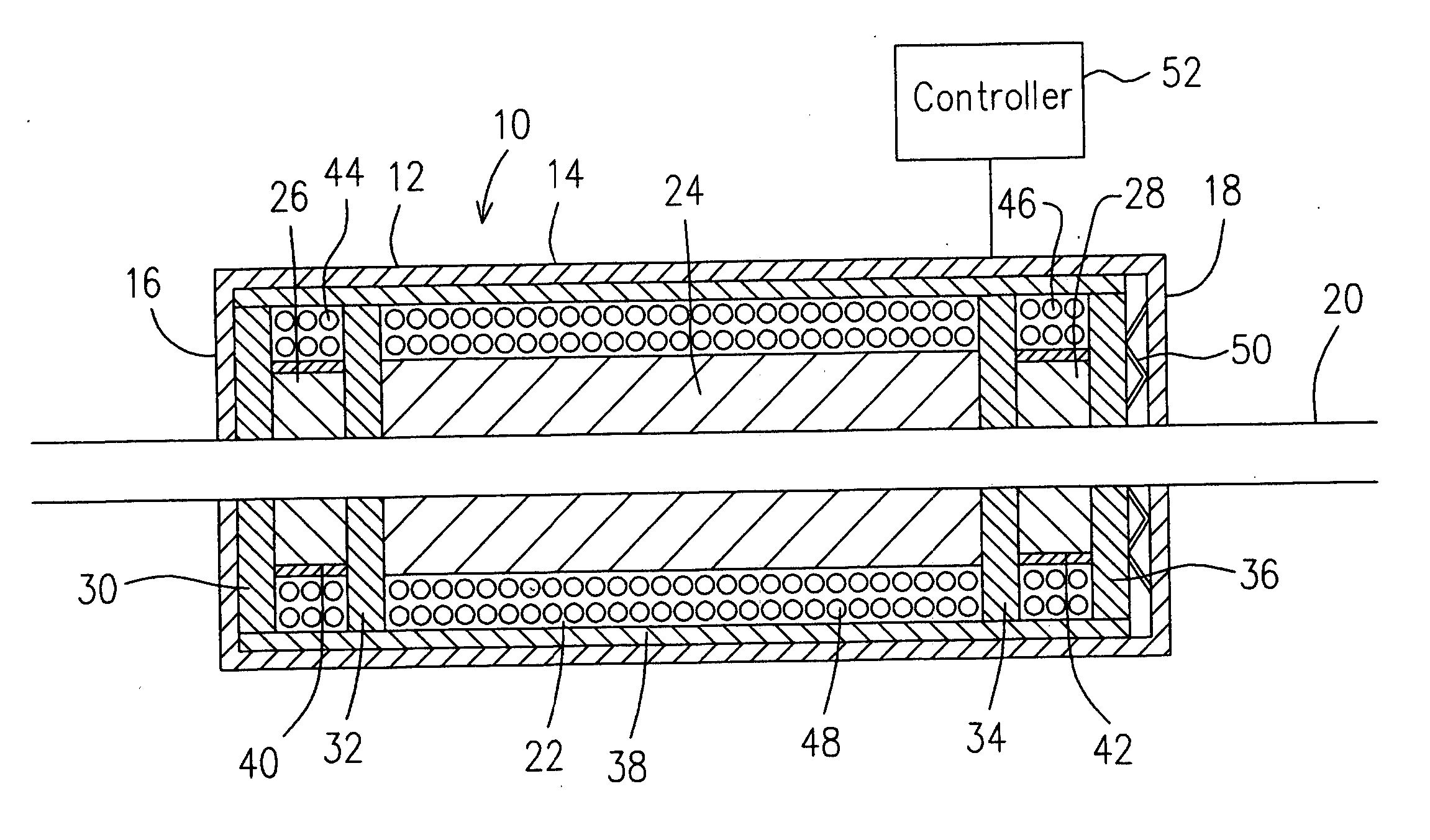
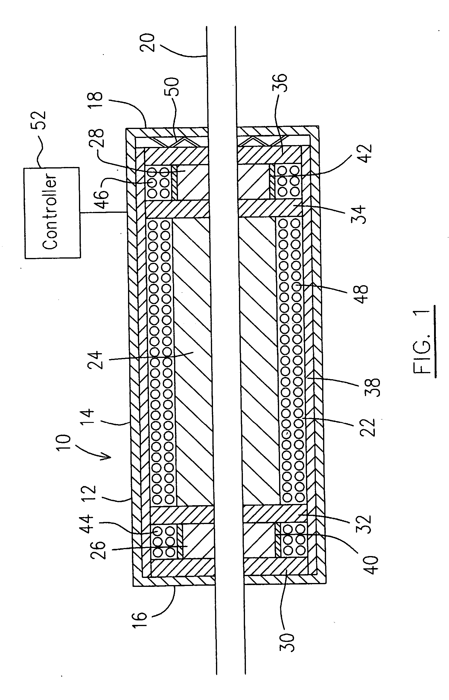
[0014] Referring to FIG. 1, an electromagnetic linear actuator in accordance with one embodiment of the present invention, generally indicated by numeral 10 includes a base structure, preferably a housing 12 having a cylindrical wall 14 axially extending between two opposed end walls 16 and 18. The respective opposed end walls 16, 18 define central openings (not indicated) therein for receiving an elongate driven member, preferably a non-magnetic steel rod 20 extending therethrough, and permitting the rod 20 to axially move in either direction relative to the housing 14. The rod 20 may not be necessarily a rigid steel rod, but may be a section of a flexible but not extendible cable, or other types, which will be further described hereinafter.

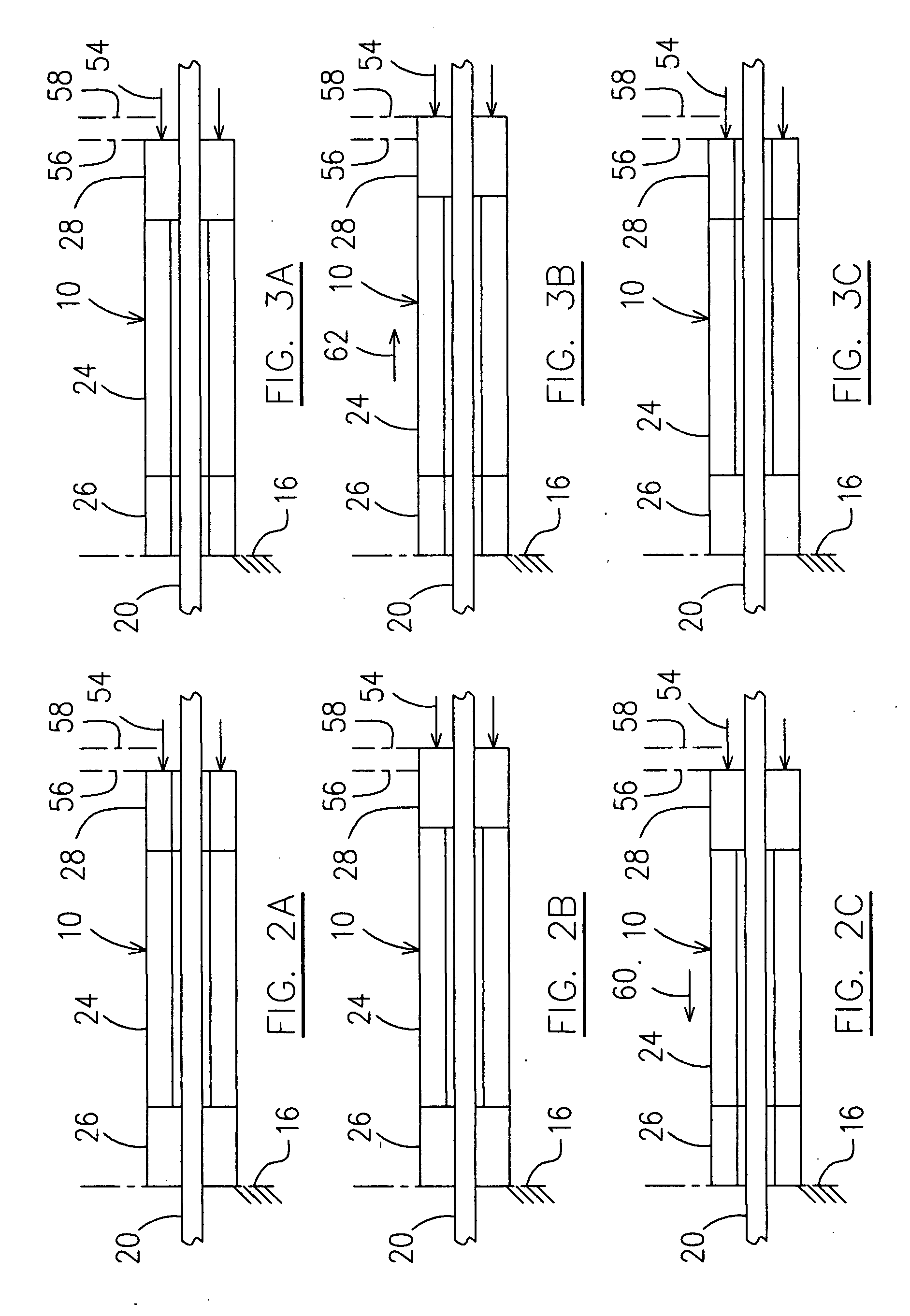
[0015] A driver assembly 22 is operatively supported within the housing 12 and includes central, first and second end elements of a magnetostrictive material, preferably a central hollow cylinder 24, first and second end hollow cylinders 26, 28...


PUM


Abstract

An electromagnetic actuator comprises an driven member and magnetostrictive elements which change the dimensions thereof when activated or deactivated by selectively applying magnetic flux therein. The driven member is moved in a selected direction when the appropriate elements are activated and deactivated in a controlled manner.

Description

FIELD OF THE INVENTION [0001] The present invention relates to actuators, more particularly to electromagnetic actuators. BACKGROUND OF THE INVENTION [0002] Electromagnetic linear actuators of an inchworm type are known and one common solution is achieved by directly moving an actuator armature in small steps using piezoelectric, electromagnetic, or magnetostrictive armature translators. Such translators can move the armature in nanometer increments, and can exert very large forces, because they rely on the stiffness of an expanding or contracting material. For example, electromagnetic linear actuators of an inchworm type are disclosed in U.S. Pat. No. 5,027,027 (Orbach et al.), U.S. Pat. No. 3,902,085 (Bizzigotti) and U.S. Pat. No. 3,902,084 (May, Jr.). The performance efficiency of the actuators disclosed in those prior art documents is limited due to the limitation of the structures thereof. [0003] Improvements to the field of electromagnetic actuators are available, however. SUM...

Claims


Application Information

Patent Timeline
IPC IPC(8): H01L29/82
CPCH01L41/12H02N2/023H10N35/00
Inventor DOOLEY, KEVIN ALLAN
Owner PRATT & WHITNEY CANADA CORP
Learn More