Gasket with compression and rotation control

a technology of rotation control and compression, applied in fluid pressure sealed joints, cable terminations, mechanical equipment, etc., to achieve the effect of reducing bending moment, reducing bending stress, and reducing bending stress

Inactive Publication Date: 2016-01-07
KOVES WILLIAM J
View PDF0 Cites 6 Cited by
  • Summary
  • Abstract
  • Description
  • Claims
  • Application Information

AI Technical Summary

Benefits of technology

[0020]The gasket sealed joint is dependent on the gasket design, the flange design and the clamping design. For “Standard Flanges” (eg. flanges to a specific standard such as ASME B16.5) the gasket is designed to work with the specified flange and bolting. For “Special Flanges” the flange, gasket and bolting are designed to optimally work together. The gasket is able to achieve greater pressure ratings than conventional raised face flanges because of several design advantages. The axial component of pressure is primarily reacted at the inner compression zone near the inside diameter close to the line of action of the applied load thereby minimizing the bending moment on the flange due to pressure and external mechanical loads. The primary bending stresses due to pressure and external mechanical loads is also reduced due to the opposing moment from the outer compression element reaction force. The flange rotation due to axial and radial pressure thrusts is also resisted by the gasket compression elements. Higher assembly loads can also be achieved because the flange stresses are displacement limited. The contact of the flange face with the gasket compression surfaces resists rotation of the flange, maintaining compression of the annular sealing element and maintaining bolt displacement. The limited rotation by the gasket also resists rotation and unloading of the annular sealing element due to thermal differentials between the flange neck and ring. The flange rotational stiffness can also accommodate some axial thermal differential between the bolts and flanges without unloading the gasket. The solid intimate contact between the gasket sealing and compression elements and the flange faces makes for more uniform temperatures between the flanges, gasket elements and bolts due to both steady state operating temperatures and transient thermal differential temperatures. The gasket also has a much greater blowout capacity than a conventional gasket design due to the wide radial width, that may extend from the inside diameter to the outside diameter, and a positive taper angle also increases the blowout resistance. The gasket also has a much greater external force and moment capacity than a conventional raised face flange / gasket design due to the wide radial width, that may extend from the inside diameter to the outside diameter creating a high effective moment of inertia. After the flange joint is assembled the typical gasket sealing element is completely contained between the inner and outer compression elements and displacement controlled. Flange rotation is limited by contact with the gasket compression elements. The gasket sealing element will see only very minor changes in compressive stress due to variations in operating pressures, external forces, and temperature differentials. The gasket stress in a conventional raised face design will vary with changes in pressure, external loads, and thermal differentials. This can lead to gasket ratcheting and leakage that is prevented by the gasket design. These features make the flange and gasket sealed joint with a gasket able to withstand greater pressures, external forces and moments, and temperature differentials than a conventional raised face flange joint.
[0021]The advantages of a rigid vs. flexible gasket in achieving more uniform gasket stress is well known to those experienced in the art of flange joint assembly. Multiple passes of bolt torque are not required. Residual compression of the outer compression zone can be achieved by a specified turn of the nut after contact. All flange and bolt stresses are displacement limited and high flange secondary stresses can be tolerated. Conventional gasket sealed joint assembly is subject to uncertainties due to elastic interaction, requiring multiple passes of bolt torque. Friction also introduces scatter in bolt torque versus load correlations resulting in less accurate assembly stresses. Physical limits on excessive flange stresses are not provided in conventional joints. The gasket design has the advantages of uniform displacement controlled sealing element stresses due to the more rigid compression elements and the advantages of the better sealing characteristics of the softer, more compliant, sealing element.
[0022]The gasket prior art describes the advantages of an outer guide ring to limit the compression of spiral wound gaskets, the advantages of joint resiliency and the use of multiple sealing surfaces. The prior art does not address the strength and stiffness of the mating flanges and clamping bolts, rigidity of the assembled joint or limiting and controlling rotation of the flanges. The theory of operation of the gasket is that the inner compression zone and sealing element are compressed with a load sufficient to “seat” and compress the sealing element and react the axial pressure thrust and the axial component of external loads and moments prior to the flange rotating the amount necessary to make contact with the outer compression zone. The residual load on the outer compression zone is sufficient to accommodate any relaxation in the joint and maintain contact. When high external bending moments are required to be accommodated greater residual compression may be required on the outer compression element and negative taper angles may be required. This would be a special, not typical, application of the gasket and assembly would be typically based on bolt torque requirements. The proper assembly load is easily achieved with a gasket with positive taper angle because the joint is assembled when the flange contacting faces make contact with the surface of the gasket at the outside diameter creating “metal to metal” contact. Any additional preload required can be easily applied by the “turn of the nut” method or other methods known to those experienced in the assembly of bolted flange joints. This is easily achieved by an assembler with little training or experience, whereas conventional gasket sealed bolted joints require trained and qualified specialists and require more bolt tightening passes and time to assemble. During the application of external static and dynamic mechanical and thermal loads the gasket compression zones remain in compression, the flange rotation is fixed and the gasket compression remains unchanged. The axial loads will be reacted by unloading the stiffer compression elements. The unloading of the inner compression element will react with the axial applied loads along a line of action close to the effective line of action of the applied loads thereby greatly reducing the bending moment on the flange as compared with a raised face flange with a conventional gasket.
[0023]Maintaining a reliable seal in a gasket sealed joint can be challenging when the operating and loading conditions are severe. Several mechanisms attempt to unload the gasket in a conventional flange joint with a gasket: axial pressure thrust, pressure rotation of the flange, dynamic hydraulic and seismic loads, axial thermal differentials, thermal rotation of the flange, gasket relaxation, and gasket ratcheting. The gasket sealed joint design addresses each of these mechanisms preventing the mechanism from degrading the seal and maintaining pressure rating while being a joint that provides for easy and reliable practical assembly in the field.

Problems solved by technology

Pressure rotation, thermal rotation, axial thermal differentials, external loads and moments and the non-linear stress strain characteristics of conventional gasket materials are all issues that lead to leakage.

Method used


Image

  • Gasket with compression and rotation control
  • Gasket with compression and rotation control
  • Gasket with compression and rotation control

Examples


Embodiment Construction

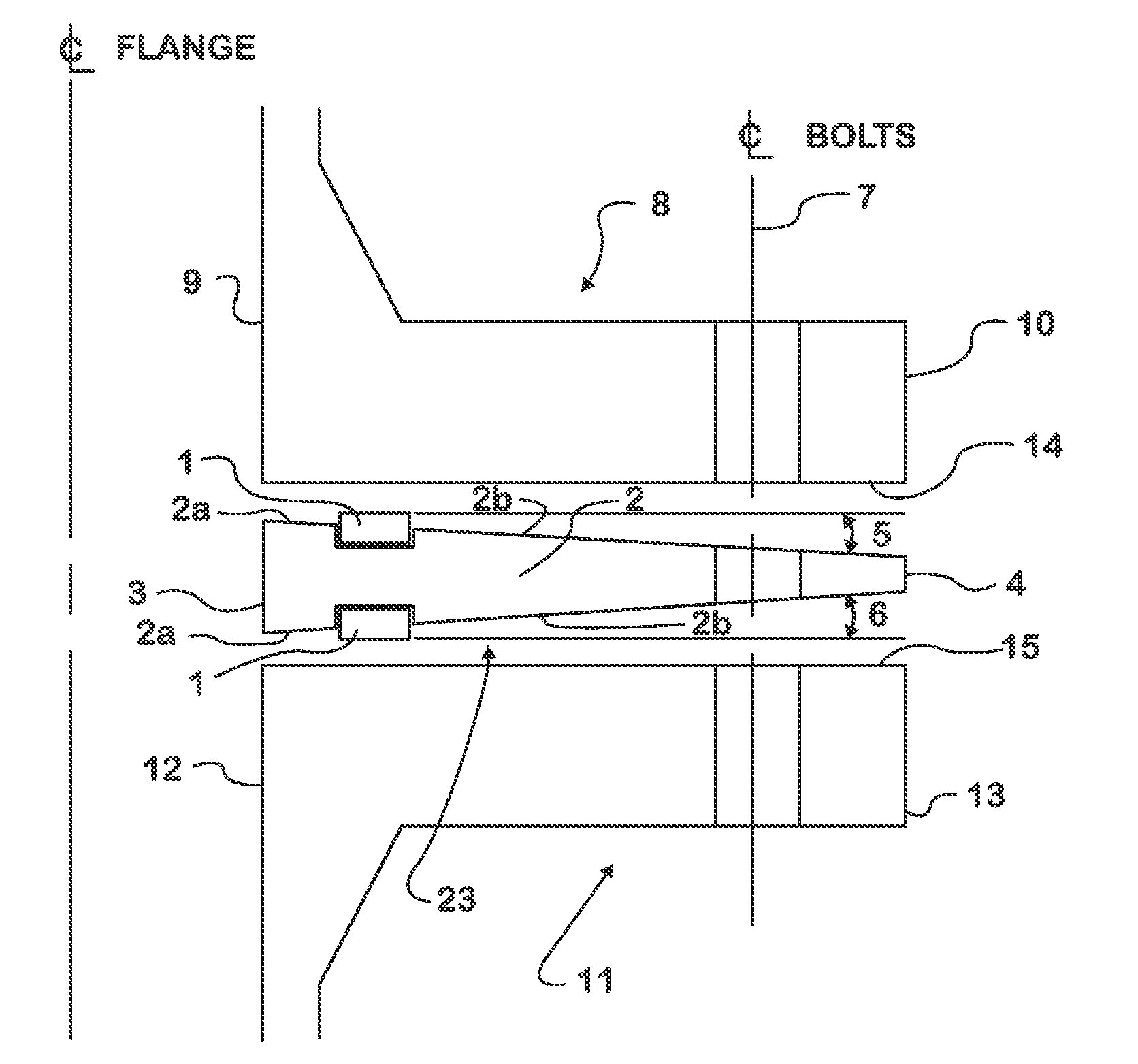
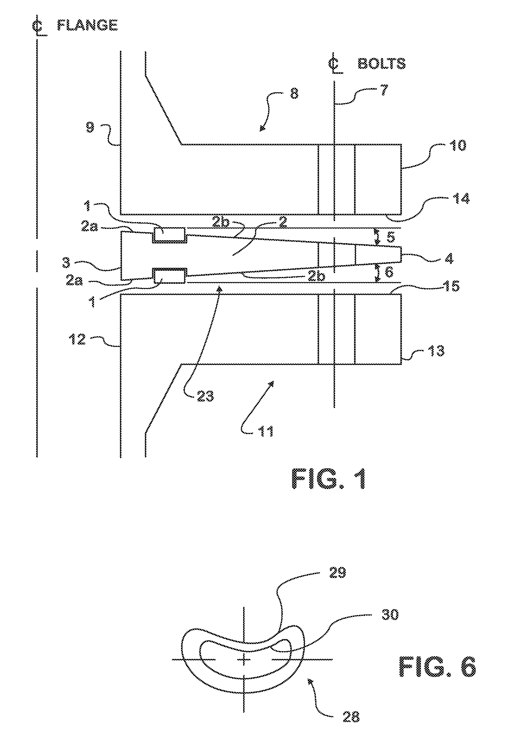
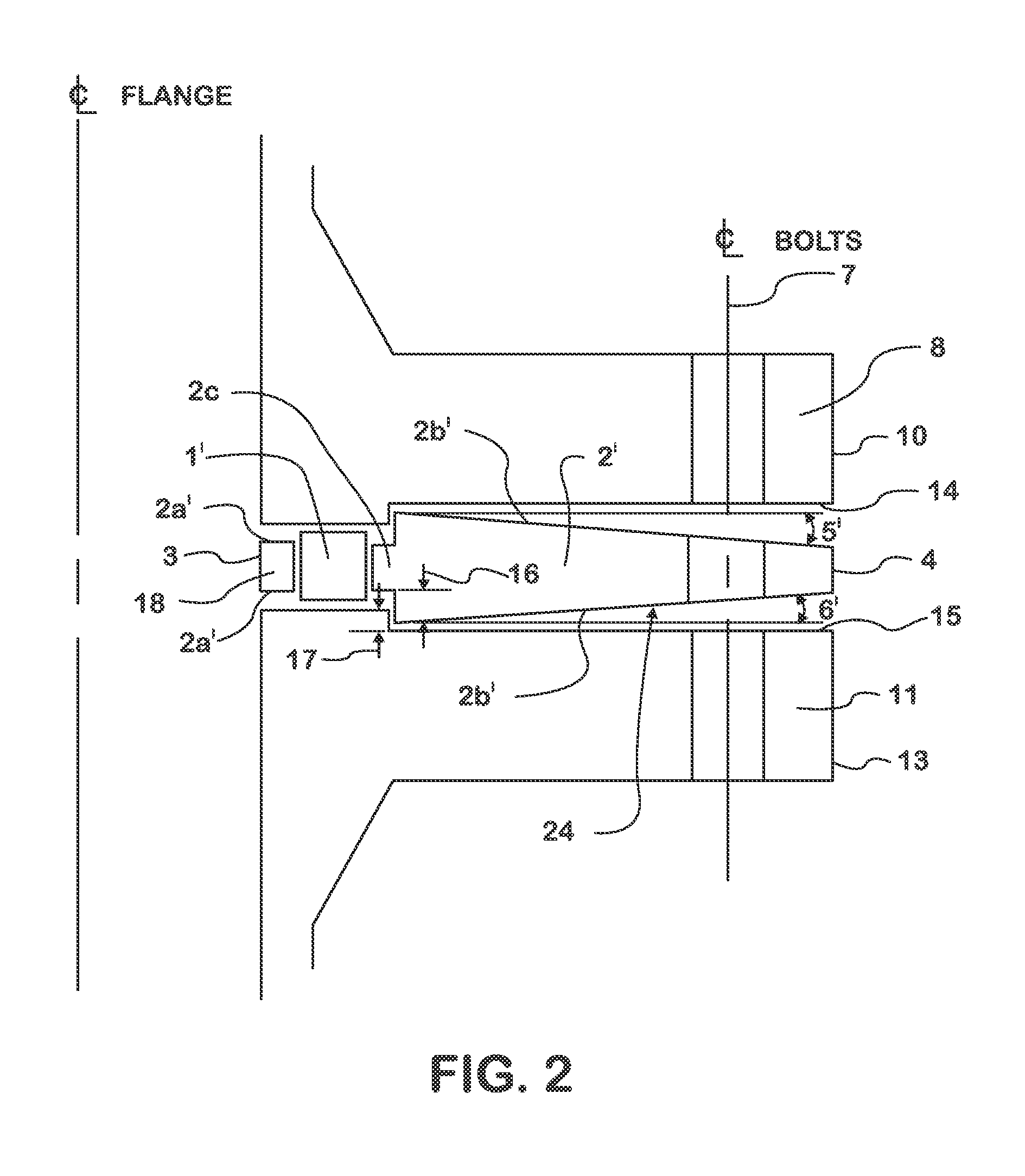
[0031]Throughout the description of this invention the following terms and associated definitions apply:

“annular sealing element”: For gaskets with an axisymmetric shape this is an annular shaped element of approximately constant radial width. For gaskets with a non-axisymmetric shape the “annular sealing element” is a shape with an inner and outer surface that approximately follows the same shape as the inner boundary of the gasket with an approximately constant width as measured normal to the inner surface of the “annular sealing element” to its outer surface (eg. the radial distance in the case of axisymmetric geometries). In all cases the “annular sealing element” is comprised of a type of construction and / or material suitable for creating a fluid tight seal, either self sealing or requiring compression and such element(s) may or may not be integral with the compression element. When the sealing element is not integral with a compression element it is comprised of a non-integral...


PUM


Abstract

A multifunctional gasket with compression and rotation control comprises annular sealing element(s) with specific stiffness, geometry, tightness and compressibility properties and uniquely shaped compression element(s) with variable thickness and specific mechanical properties. The gasket is designed to seal under static and dynamic fluid pressure loading for a wide range of sizes and with severe thermal differential temperatures and static and dynamic external loads. This gasket is able to significantly increase the pressure rating for leakage, ability to resist external forces and moments, resistance to thermal differentials and operating reliability of flanges in accordance with published standards, as well as enable the more efficient design of special flanges for demanding operating conditions. The gasket design also allows for easier, faster and more uniform assembly of the joint.

Description

BACKGROUND OF THE INVENTION[0001]1. Field of the Invention[0002]The invention described herein is in the field of fluid containment at clamped conduit or chamber connections. In a general form the invention relates to joining conduits or chambers, each defining a connection body about an open end thereof, by a sealing structure clamped between opposing connection bodies defined at the end of the conduits or chambers. These connections are provided to prevent fluid leakage into or out of the chambers or conduit under temperature conditions, internal pressure loads, and / or external forces. In more specific form this invention provides a sealing structure, typically, in the form of a gasket, which is adapted when clamped between connection bodies, typically in the form of flanges, to seal the gap between the connection bodies around a chamber or conduit jointly defined by the connection bodies as the space there between. The sealing structure of this invention may be used, for example,...

Claims


Application Information

Patent Timeline
Patent Type & Authority Applications(United States)
IPC IPC(8): F16L23/20F16J15/08
CPCF16J15/0887F16L23/20F16L23/18F16L23/24
Inventor KOVES, WILLIAM, J.
Owner KOVES WILLIAM J
Why Eureka
Try Eureka