
Swing arm manipulator

A technology of manipulator and arm plate, which is applied in the field of medical equipment, can solve the problems of broken cuvettes, difficult control, and inconvenient use, and achieves the effects of easy movement, compact structure, and small appearance

Pending Publication Date: 2018-04-24
苏州立禾生物医学工程有限公司
View PDF0 Cites 0 Cited by
  • Summary
  • Abstract
  • Description
  • Claims
  • Application Information

AI Technical Summary

Problems solved by technology

Inconvenient to use, difficult to control, and easy to pinch the cuvette

Method used


Image

  • Swing arm manipulator
  • Swing arm manipulator
  • Swing arm manipulator

Examples


Embodiment Construction

[0029] The present invention is described in further detail now in conjunction with accompanying drawing. These drawings are all simplified schematic diagrams, which only illustrate the basic structure of the present invention in a schematic manner, so they only show the configurations related to the present invention.

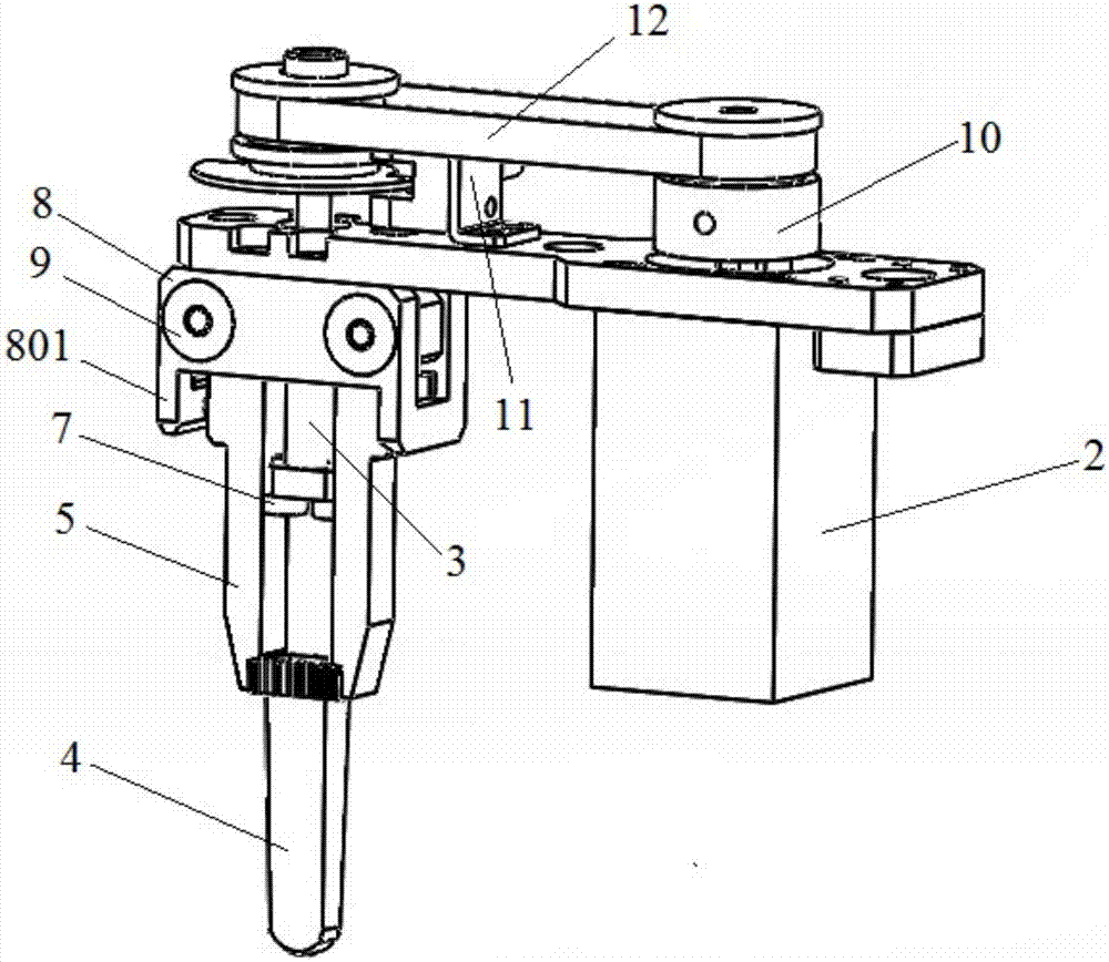
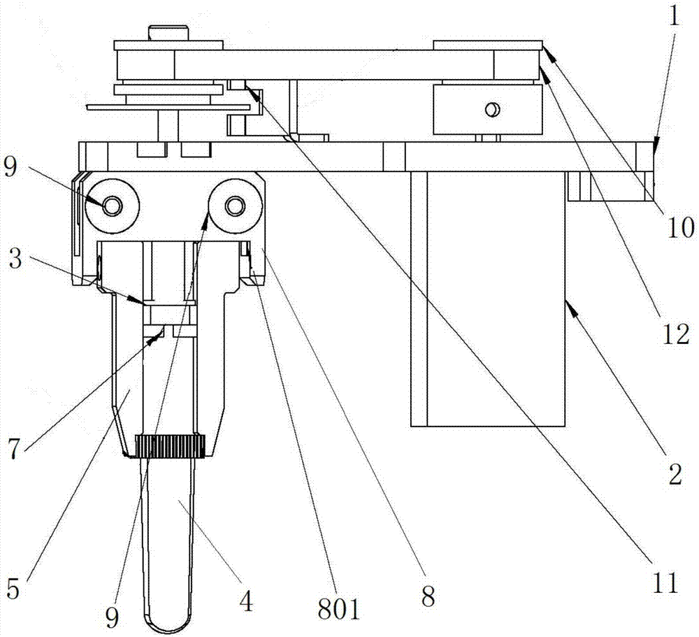
[0030] Such as Figure 1-4 As shown, the present embodiment provides a swing arm manipulator, including a fixed plate 1 and a drive mechanism 2, the fixed plate 1 is provided with a swing assembly, the swing assembly includes a rotating shaft 3 and two groups of swing arm components; two groups of swing arm components are used for To clamp the cuvette 4, two sets of swing arm components are arranged symmetrically on both sides of the rotating shaft 3. The swing arm components include a swing arm 5 and an elastic member 6 for clamping the swing arm. Positioning element 7, the driving mechanism 2 drives the rotating shaft 3 to rotate forward or backward, and th...


PUM


Abstract

The invention relates to a swing arm manipulator including a fixing plate and a driving mechanism. The swing arm manipulator is characterized in that the fixing plate is provided with a swing assemblywhich includes a spindle and two groups of swing arm elements; and the two groups of swing arm elements are used to clamp a reaction cup and are symmetrically arranged at two sides of the spindle, the swing arm elements includes swing arms and flexible assemblies which are used to clamp the swing arms, a limit element is arranged between the swing arms and the spindle, the driving mechanism drives the spindle to rotate in a forward direction or a backward direction, and the limit element can prop the swing arms open or clamp the swing arms which are arranged at two sides of the limit elementthrough rotating of the spindle to open or clamp the reaction cup. According to the swing arm manipulator, the driving mechanism drive the spindle to rotate through the forward rotating and the backward rotating, and the limit element can enable the swing arm to prop open and clamp through the rotating of the spindle to open and clamp the reaction cup; and the use is convenient, the appearance issmall and exquisite, the reaction cup can be clamped in a high speed, and the requirement of rapid swing of the reaction cup can be met.

Description

technical field [0001] The invention relates to a manipulator, in particular to a swing arm manipulator, which belongs to the technical field of medical devices. Background technique [0002] At present, the manipulators in automatic chemiluminescence detectors are generally relatively large and have a large moment of inertia. The clamping force is also relatively large, which needs to be controlled by the output of the motor. It is inconvenient to use, difficult to control, and it is easy to crush the cuvette. [0003] Therefore, inventing and designing a kind of structure is small and exquisite, and motion inertia is little, and the manipulator that is easy to control becomes a kind of development trend. Contents of the invention [0004] The technical problem to be solved by the present invention is: in order to solve the technical problem, a swing arm manipulator is provided, so that the cuvette can be put down or clamped through the positive and negative rotation of...

Claims


Application Information

Patent Timeline
Patent Type & Authority Applications(China)
IPC IPC(8): B65G47/90
CPCB65G47/90B65G2201/02
Inventor 申峰波周方芳田阳徐炯宽
Owner 苏州立禾生物医学工程有限公司
Learn More