
Reflective fluidics matrix display particularly suited for large format applications

a fluidics matrix and display technology, applied in the field of display subsystems, can solve the problems of inability to the cmy model cannot reproduce the brightness of rgb colors, and the cmy model is usually not used alon

Inactive Publication Date: 2006-09-07
CYMSCAPE
View PDF2 Cites 28 Cited by
  • Summary
  • Abstract
  • Description
  • Claims
  • Application Information

AI Technical Summary

Benefits of technology

[0023] It is a primary object of the present invention to provide an inactive display that is free of any internal illumination source and that uses a CMYK process and is particularly suited to serve the needs of outdoor advertising.
[0024] It is another object of the present invention to provide a fluidics matrix display that utilizes the mixture techniques of the CMYK process to supply an image thereof and that may be updated or changed in a relatively rapid manner.
[0026] In addition, it is an object of the present invention to provide a relatively simple switching arrangement to control the activation of the pixel assemblies of the display while at the same time reducing the number of pneumatic valves that are involved.

Problems solved by technology

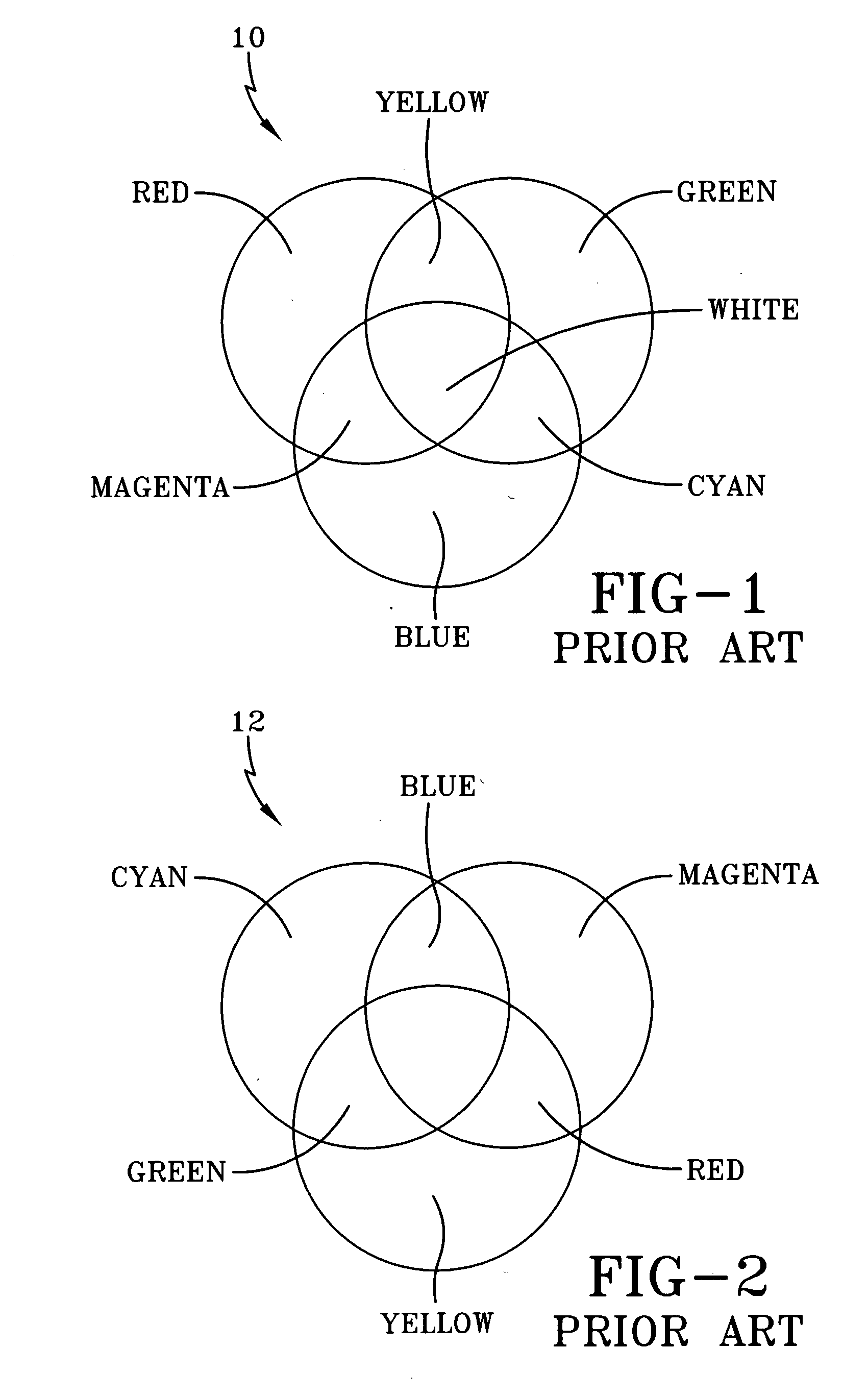
However, the colors created by the subtractive model of CMY do not exactly look like the colors created in the additive model of RGB.
Particularly, the CMY model cannot reproduce the brightness of RGB colors.
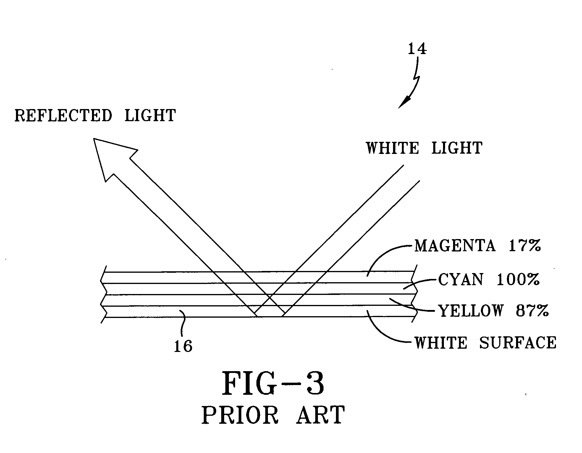
In practice, however, CMY usually cannot be used alone because imperfections in the inks and other limitations of the process mean full and equal absorption of the light are not possible.
Because of these imperfections, true black or true grays cannot be created by mixing the inks in equal proportions.
The actual result of doing so results in a muddy brown color.

Method used


Image

  • Reflective fluidics matrix display particularly suited for large format applications
  • Reflective fluidics matrix display particularly suited for large format applications
  • Reflective fluidics matrix display particularly suited for large format applications

Examples


Embodiment Construction

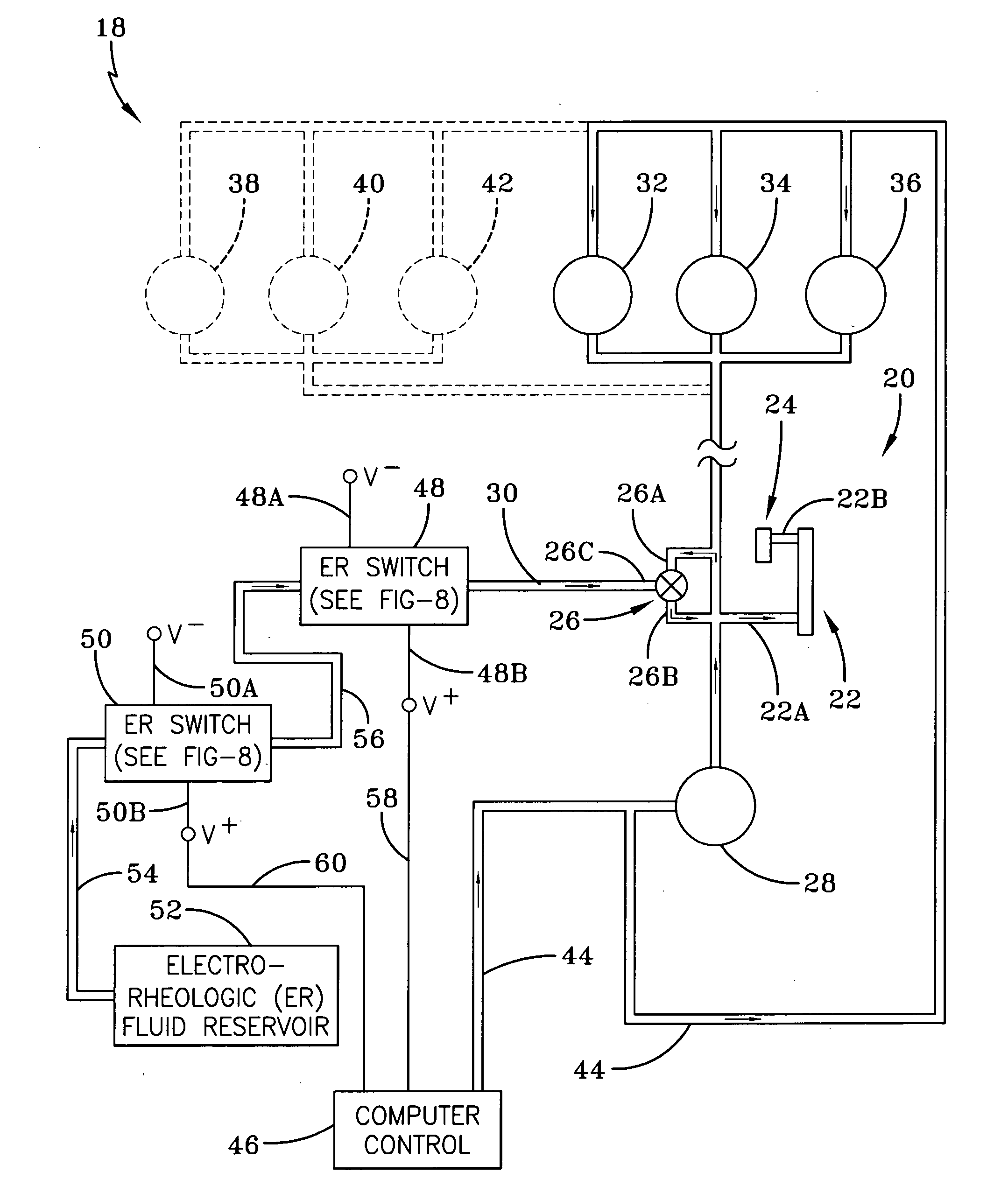
[0043] The reflective fluidics matrix display system 18 of the present invention, shown in FIG. 4, is passive, in that, it relies on illumination from outside the display to strike the display and illuminate the image as opposed to an active display that produces illumination for the image from within.

[0044] In general, and as will be further described in detail, the fluidics matrix display 18 is a reflective display that utilizes four overlapping layers of colored die to create an image. Each of the four layers corresponds to one color in the CMYK color space. Each of the pixel elements of the fluidics matrix display 18 is individually addressable and is composed of four stacked pixel chambers making up one of the colors in the CMYK color space. More particularly, each of the four-stacked pixel chambers is individually addressable. Each of the four-pixel chambers is valved to admit or expunge the colored fluid or die to or from that chamber. Images are created by writing the appro...


PUM


Abstract

A fluid matrix display is disclosed which is a reflective display that utilizes four colored dyes to create an image. Each of the dyes corresponds to one color in a CMYK color space. Each individually addressable pixel element of the fluid matrix display is composed of four-stacked pixel chambers. Images are created by writing appropriate colored dye data into each pixel chambers of each pixel element of the fluid matrix display. Each pixel chamber is valved to admit or expunge the colored dye to and from that pixel chamber. The admitting and expunging is controlled by the use of electrorhelogic fluids, which provides for a relatively simple switching arrangement to activate and deactivate the pixel assemblies.

Description

CROSS REFERENCE TO RELATED APPLICATIONS [0001] This application is related to U.S. patent application Ser. No. 10 / 988,279 filed Nov. 13, 2004. This application is also related to U.S. patent application Ser. No. ______ having Attorney Docket No. SP 004 and filed herewith.FIELD OF THE INVENTION [0002] The invention relates to display subsystems and, more particularly, to a reflective microfluidics display particularly suited for large format applications that relies upon illumination from outside the display to strike the display and illuminate the image thereof, as opposed to an active display that produces illumination from within and consumes relatively more power thereof BACKGROUND OF THE INVENTION [0003] All displays, whether active or passive, must adhere to a color model. Red, green, blue (RGB) and its subset cyan, magenta, yellow (CMY) form the most basic and well-known color models. These models bear the closest resemblance to how humans perceive color. These models also cor...

Claims


Application Information

Patent Timeline
Patent Type & Authority Applications(United States)
IPC IPC(8): G09G3/34
CPCG09G3/34
Inventor SIKORA, ROBERT M.MCMAHON, SEAN P.
Owner CYMSCAPE
Learn More