Magnetic detectible head comprising free layer

Active Publication Date: 2006-09-07
TDK CORPARATION
View PDF12 Cites 0 Cited by
  • Summary
  • Abstract
  • Description
  • Claims
  • Application Information

AI Technical Summary

Benefits of technology

[0015] The invention has been made to solve the above conventional problems. It is therefore the object of the invention to provide a magnetic detecting element with high reproducing output by presenting preferable configuration conditions of a free magnetic layer.

Problems solved by technology

However, even if the free magnetic layer is formed using the NiFe alloy in this range of composition, it was difficult to control the product ΔRA of the resistance variation of a CPP (Current Perpendicular to the Plane)—GMR magnetic detecting element in which a sensing current as a direct current is allowed to flow perpendicularly to the surface of the multilayer film, and the area of the element so as to be 5 mΩμm2 or more.
As a result, a practical producing output cannot be obtained.

Method used


Image

  • Magnetic detectible head comprising free layer
  • Magnetic detectible head comprising free layer
  • Magnetic detectible head comprising free layer

Examples


example 1

[0095] The product ΔRA of the magnetic resistance variation ΔR and the element area A, when a dual spin valve type magnetic detecting element having the film composition shown below was formed and the at % of Ni in the NiaFeb alloy layer (where a and b are represented by at %, and a+b=100) constituting the free magnetic layer was changed, was investigated.

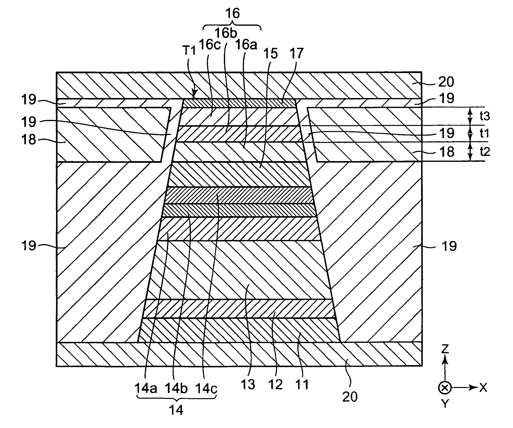
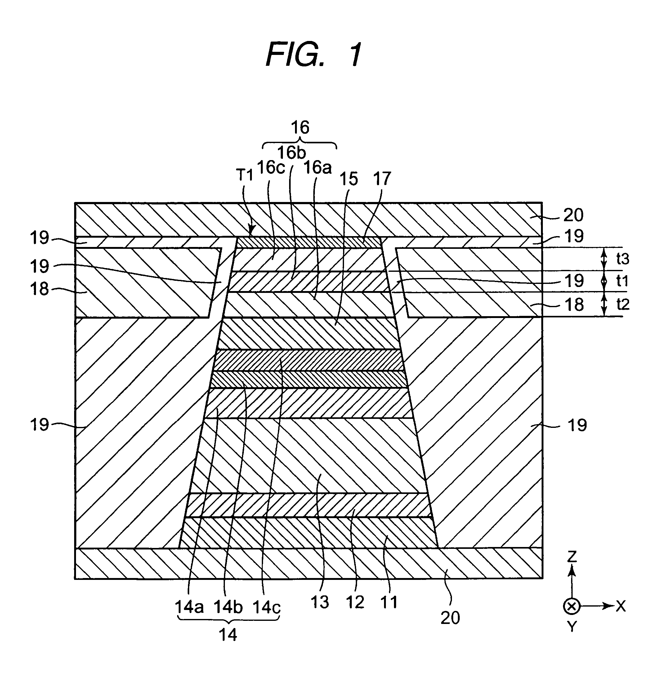
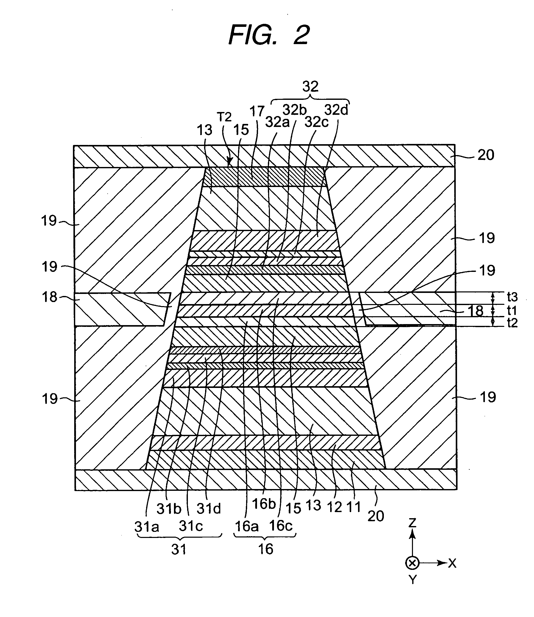
[0096] The dual spin valve type magnetic detecting element included: Substrate / foundation layer Ta (30 Å) / seed layer NiFeCr (50 Å) / antiferromagnetic layer IrMn (70 Å) / fixed magnetic layer [first fixed magnetic layer Co70Fe30) (30 Å) / nonmagnetic intermediate layer Ru (9.1 Å) / second fixed magnetic layer CoFe (10 Å) / Co2MnGe (40 Å)] / nonmagnetic material layer Cu (43 Å) / free magnetic layer CoFe (5 Å) / NiaFeb (90 Å) / CoFe (5 Å) / nonmagnetic material layer Cu (43 Å) / second fixed magnetic layer (Co2MnGe (40 Å) / CoFe (10 Å) / nonmagnetic intermediate layer Ru (9.1 Å) / first fixed magnetic layer (Co70Fe30 (30 Å)) / antiferromagnetic layer IrMn (70 Å...


PUM


Abstract

There is provided a magnetic detecting element having a large ΔRA. A free magnetic layer has a three layer structure in which a CoFe layer, an NiaFeb alloy layer (where a and b are represented by at %, 0≦a≦25, and a+b=100), and a CoFe layer are laminated from the bottom. If the at % of Ni in an NiFe alloy that exists in the free magnetic layer is in this range, a spin-dependent bulk scattering coefficient β increases, and the product ΔRA of the resistance variation of the magnetic detecting element and the area of the element can be made increased.

Description

BACKGROUND OF THE INVENTION [0001] 1. Field of the Invention [0002] The present invention relates to a CPP (current perpendicular to the plane) type magnetic detecting element that allows a sense current to flow in a direction perpendicular to the surface of a film, and more specifically, to a magnetic detecting element that can make greater the product ΔRA of the resistance variation and area of the element. [0003] 2. Description of the Related Art [0004]FIG. 5 is a partially cross-sectional view of a conventional magnetic detecting element (spin valve type thin film element) when it is cut from the direction parallel to a surface facing a recording medium. [0005] Reference numeral 1 shown in FIG. 5 is a foundation layer made of Ta, and a seed layer 2 made of a metal having a bcc structure (body-centered cubic structure), such as Cr, is formed on the foundation layer 1. [0006] On the seed layer 2, a multilayer film T in which an antiferromagnetic layer 3, a fixed magnetic layer 4, ...

Claims


Application Information

Patent Timeline
IPC IPC(8): G11B5/127G11B5/33
CPCB82Y25/00G11B5/3903G11B5/3932H01F10/3295H01F10/3281H01L43/10H01F10/1936H10N50/85
Inventor IDE, YOSUKESAITO, MASAMICHIISHIZONE, MASAHIKOHASEGAWA, NAOYA
Owner TDK CORPARATION
Why Eureka
Try Eureka