Magnetic resistance head and making method thereof

A magneto-resistive and magnetic head technology, which is applied in the manufacture of magnetic flux-sensitive magnetic heads, magnetic recording heads, magnetic recording, etc., can solve problems such as poor contact, difficulty in aligning MR films with contact holes, etc., and achieve high yield and easy manufacturing Effect

Inactive Publication Date: 2008-02-06
FUJITSU LTD
View PDF2 Cites 0 Cited by
  • Summary
  • Abstract
  • Description
  • Claims
  • Application Information

AI Technical Summary

Problems solved by technology

On the other hand, current photolithography has an error of about 0.06 microns
Accordingly, as the MR film becomes finer, the alignment of the MR film with the contact hole becomes difficult in the conventional contact hole process.
On the other hand, the stripping process also has problems such as poor contact due to a part of photoresist remaining after stripping.

Method used


Image

  • Magnetic resistance head and making method thereof
  • Magnetic resistance head and making method thereof
  • Magnetic resistance head and making method thereof

Examples


Embodiment Construction

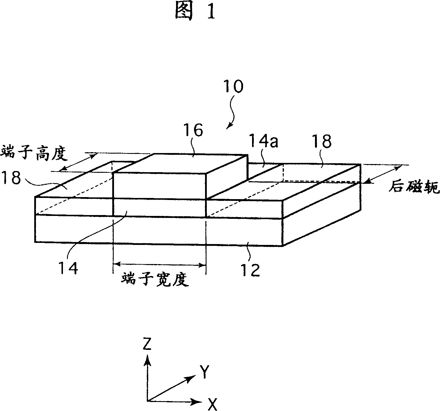
[0051] Some preferred embodiments of the present invention are described below with reference to the accompanying drawings. In the following description of the preferred embodiment, substantially the same parts are denoted by the same reference numerals. Referring to FIG. 1, there is shown a perspective view of a magnetoresistive head 10 according to a first preferred embodiment of the present invention. In Fig. 1, the upper and lower magnetic shields are not shown. Figure 12 shows the lower electrode terminal formed of copper or a combination of copper and gold. The lower electrode terminal 12 has a first width in the X direction shown in FIG. 1 and a first height in the Y direction described in FIG. 1 .

[0052] A magnetoresistive film (MR film) 14 is formed on the lower electrode terminal 12 . The MR thin film 14 has a second width smaller than the first width in the X direction and has a height equal to the first height in the Y direction. A pair of magnetic domain con...


PUM

PropertyMeasurementUnit
thicknessaaaaaaaaaa

Abstract

A magnetoresistive head includes a first magnetic shield, a first electrode terminal provided on the first magnetic shield and having a first width or height, and a magnetoresistive film provided on the first electrode terminal and having a second width or height less than or equal to the first width or height. The magnetoresistive head further includes a second electrode terminal provided on the magnetoresistive film and having a third width or height less than or equal to the second width or height, and a second magnetic shield provided on the second electrode terminal. Preferably, the magnetoresistive head further includes a plug electrode for connecting the second electrode terminal to the second magnetic shield, and a plug side wall protective insulating film for covering a side wall of the plug electrode.

Description

technical field [0001] The present invention relates to a magnetoresistive head for use in magnetic recording devices such as disk drives and tape drives. Background technique [0002] With the reduction in size of disk drives and the increase in recording density in recent years, the flying height of the head slider has become smaller, and it is necessary to achieve contact recording / reproduction so that the head slider is very small above the recording medium Float at a height of 100,000, or come into contact with the recording medium. In addition, the conventional magnetic induction head has a disadvantage such that its reproduction output decreases as the peripheral velocity (relative speed between the head and the medium) of the magnetic disk as the recording medium decreases due to the reduction of the diameter of the magnetic disk, for example. In order to solve this disadvantage, a magnetoresistive head (MR head) whose reproduction output does not depend on the peri...

Claims


Application Information

Patent Timeline
Patent Type & Authority Patents(China)
IPC IPC(8): G11B5/39
CPCB82Y10/00G11B5/3909B82Y25/00G11B5/3903G11B2005/3996Y10T29/49046G11B5/39
Inventor 芦田裕江口伸田中厚志近藤玲子清水丰
Owner FUJITSU LTD
Why Eureka
Try Eureka