Developing device and image forming device equipped with same

Active Publication Date: 2006-09-07
KYOCERA DOCUMENT SOLUTIONS INC
View PDF2 Cites 16 Cited by
  • Summary
  • Abstract
  • Description
  • Claims
  • Application Information

AI Technical Summary

Benefits of technology

[0013] According to the third aspect of the present invention, the discharge flow of the developer outside the development area can be effectively controlled in the same manner with a simple construction, and stable sealing capability can be achieved over a long period of time, as a result of enabling the developer retained on the peripheral surface of the development sleeve to be guide

Problems solved by technology

However, one problem is that sufficient sealing capability will not achieved with a construction which provides only the magnetic sealing member as described in the prior art.
Therefore, when this pushing force becomes greater than the magnetic confinement of the magnetic sealing member, the magnetic toner cannot be completed prevented from esc

Method used


Image

  • Developing device and image forming device equipped with same
  • Developing device and image forming device equipped with same
  • Developing device and image forming device equipped with same

Examples


Example

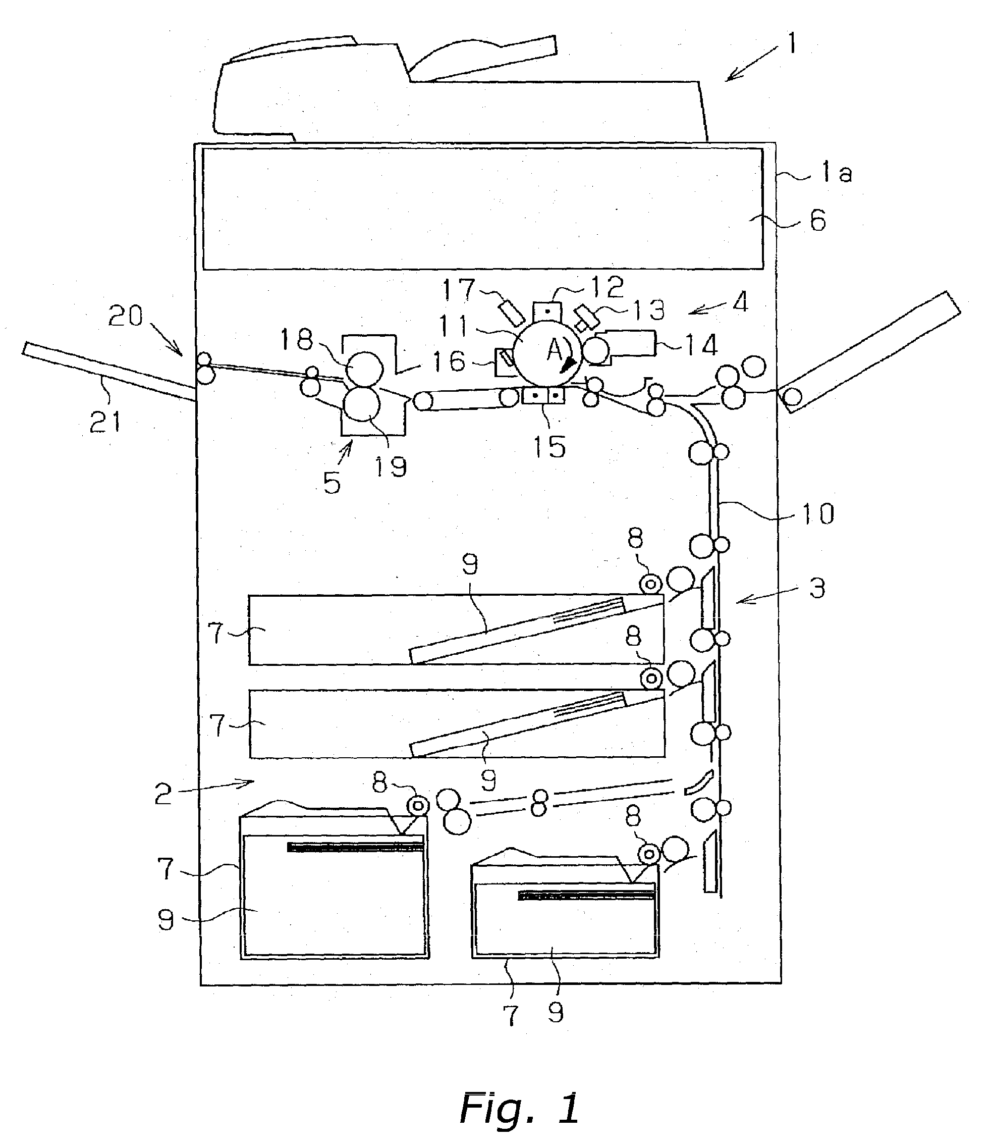
[0031] A detailed description of a preferred embodiment of the present invention is provided hereinafter with reference to the drawings. FIG. 1 is a schematic diagram showing the overall structure of an image forming device according to an embodiment of the present invention. As shown in FIG. 1, an image forming device 1 comprises a paper supply unit 2 arranged on the lower portion of an image forming device main unit 1a, a paper feeding unit 3 arranged to the side and above the paper supply unit 2, an image forming unit 4 arranged above the paper feeding unit 3, a fusing unit 5 arranged more to the discharge side than the image forming unit 4, and an image reading unit 6 arranged above the image forming unit 4 and the fusing unit 5.

[0032] The paper supply unit 2 comprises a plurality of paper supply cassettes 7 (four cassettes in this embodiment) where paper is placed, and a paper supply roller 8 provided above the paper supply unit 7. Paper 9 is delivered to the paper feeding uni...


PUM


Abstract

A developing device is disclosed which includes a fixed magnet roller 25 having a plurality of magnetic poles, a development roller 27 having a development sleeve 26 that is supported axially with the ability to rotate freely, and a magnetic sealing member 29 arranged at the end of the longitudinal direction X of the development sleeve 26. Further, the length of each of the plurality of magnetic poles not facing the magnetic sealing member 29 (in other words, the development pole S1, lead-in pole N1, and blade pole N3) of the fixed magnet roller 25 are shorter than the length of each of the plurality of magnetic poles facing the magnetic sealing member 29. Accordingly, the magnetic toner retained on the peripheral surface of the development sleeve 26 is guided to the development area side in the longitudinal direction X of the development sleeve 26.

Description

BACKGROUND OF THE INVENTION [0001] 1. Field of the Invention [0002] The present invention relates to a developing device that uses developer to develop by means of an electrophotography development method, and more particularly to a developing device for preventing the scattering of developer outside the development area, and an image forming device equipped with same. [0003] 2. Background Information [0004] Image forming devices such as printers, facsimiles, copying machines, etc. using an electrophotography development method are generally equipped with a photoreceptor and a developing device. An electrostatic latent image based on image data is formed on the surface of the photoreceptor, and a toner image is formed by developing this electrostatic latent image by means of a developing device that contains a developer. [0005] Such conventional developing devices further provide a sealing member in order to prevent discharge of the toner outside of the development area. For instanc...

Claims


Application Information

Patent Timeline
IPC IPC(8): G03G15/09
CPCG03G15/0921
Inventor KOTERA, ASAMINIMURA, EIJI
Owner KYOCERA DOCUMENT SOLUTIONS INC
Why Eureka
Try Eureka