
Reinforced cleaning member and process cartridge and image forming apparatus using same

a cleaning member and a technology of a process cartridge, applied in the field of cleaning members, can solve the problems of reducing the accuracy of not addressing the need for accurate blade contact with the image carrier, and not correctly removing toner from the image carrier, so as to prevent or reduce noise, improve the effect of contact accuracy

Inactive Publication Date: 2006-09-07
RICOH KK
View PDF2 Cites 0 Cited by
  • Summary
  • Abstract
  • Description
  • Claims
  • Application Information

AI Technical Summary

Benefits of technology

[0009] It is an object of the present invention to provide a cleaning member, process cartridge and image forming apparatus that improve the accuracy of contact between the cleaning blade and image carrier.
[0010] It is yet another object of the present invention to provide a cleaning member, process cartridge and image forming apparatus that prevent or reduce noises occurring from oscillation of the cleaning blade.

Problems solved by technology

While this configuration maintains a good toner removing efficiency for high speed machines, it decreases the accuracy of blade contact on the image carrier.
However, this reference does not address the need for accuracy of blade contact with the image carrier.
Because the cleaning member of the above described publications do not provide accurate contact between the blade and image carrier, the devices disclosed therein generally do not remove toner from the image carrier correctly.
Moreover, the present inventors have recognized that inaccuracy of the contact point between the blade and image carrier may undesirably transform the image carrier.
Furthermore, it is generally known that when a cleaning blade non-uniformly contacts an image carrier, undesirable noise results, perhaps due to oscillations of the cleaning blade.
However, it has been difficult to completely prevent noises because of the many factors that contribute to this problem, which include a photoreceptor structure, a toner type, and a cleaning blade type, as well as temperature and humidity of the operating environment.

Method used


Image

  • Reinforced cleaning member and process cartridge and image forming apparatus using same
  • Reinforced cleaning member and process cartridge and image forming apparatus using same
  • Reinforced cleaning member and process cartridge and image forming apparatus using same

Examples


Embodiment Construction

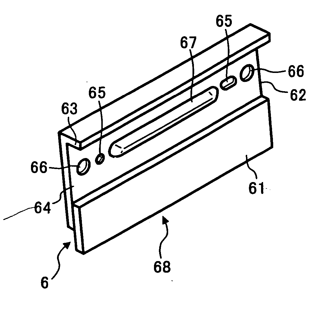
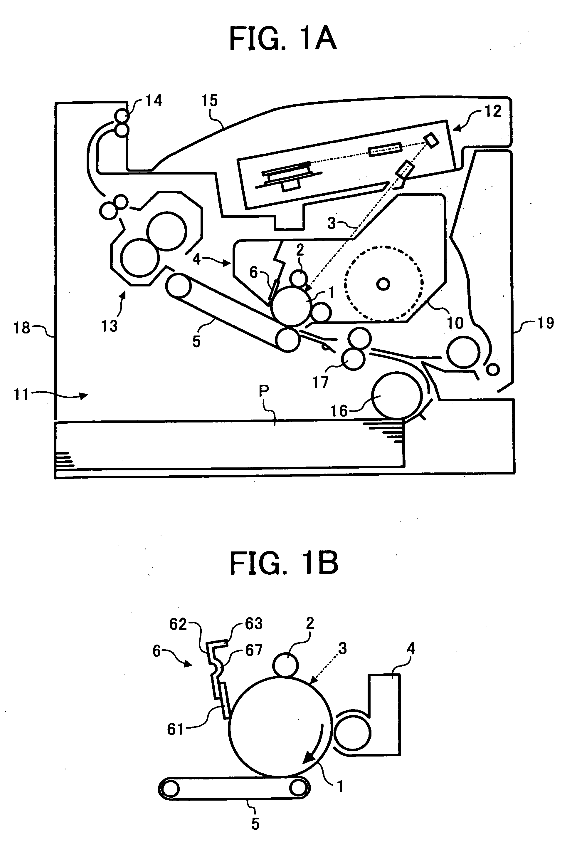
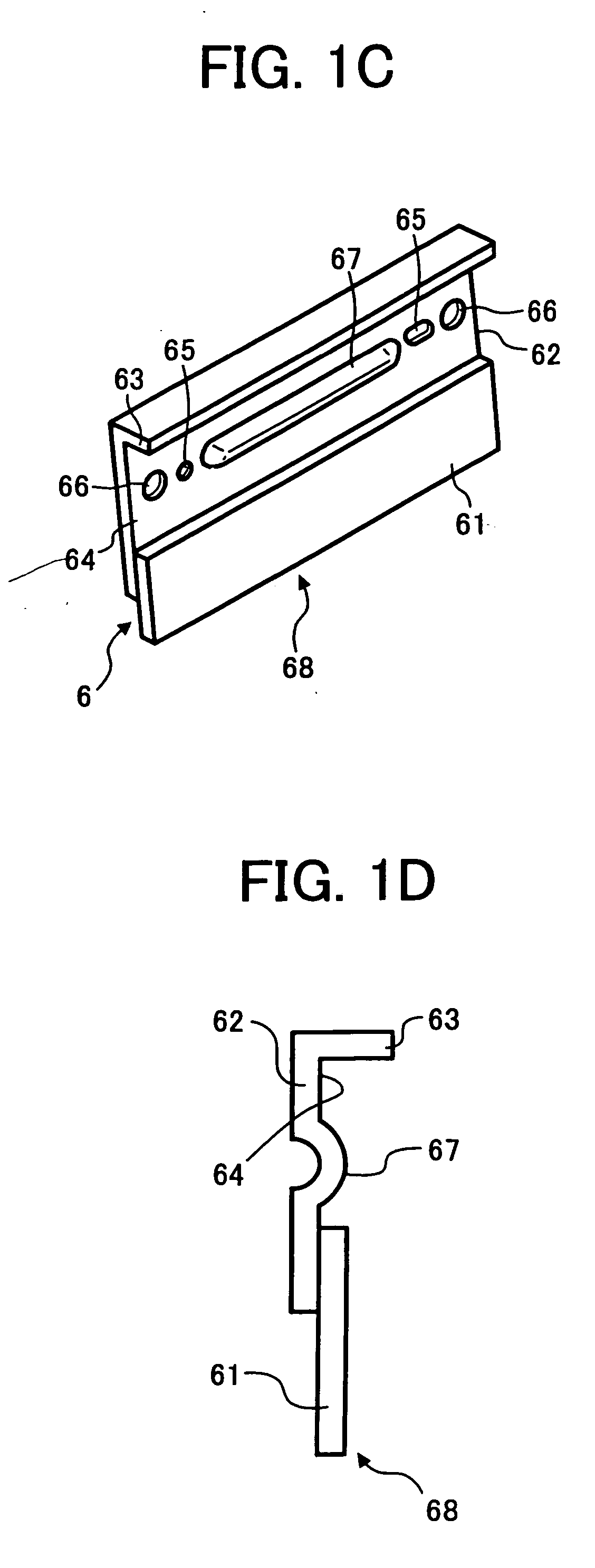
[0030] A cleaning member, image process cartridge, and image forming apparatus of the present invention will be explained below with the reference to the accompanying drawings. The invention will be explained with reference to a process cartridge; however, it is to be understood that the invention can be applied to an image forming apparatus without using a process cartridge.

[0031] Referring now to the drawings, FIG. 1A shows an outline constitution of a printer according to an embodiment of the present invention. As seen in this figure, the image forming apparatus 18 includes an image carrier 1, charging device 2, a light 3 from laser writing unit 12, a developing device 4, a transfer device 5, and a cleaning member 6. The embodiment of FIG. 1A includes a process cartridge 10 which includes the image carrier 1, charging device 2, developing device 4 and cleaning member 6 in one unit. In addition, the apparatus includes paper feed 11, fixing device 13, a pair of eject rollers 14, e...


PUM


Abstract

A cleaning member for cleaning an image carrier. The cleaning member includes a support plate having a planar face portion configured to be fixed to an object in a position adjacent to the image carrier, a plurality of reinforcement features configured to reinforce a strength of the support plate, at least one of the reinforcement features arranged on the planar face portion, and a blade connecting portion arranged on the planar face portion. The cleaning member further includes an elastic blade member connected to the blade connecting portion of the support plate such that the elastic blade extends toward the image carrier when the support plate is fixed to the object. The image cleaner may be positioned within an image forming apparatus or an image developing cartridge.

Description

CROSS REFERENCE TO RELATED APPLICATIONS [0001] This application is a continuation of application Ser. No. 10 / 712,038, filed Nov. 14, 2003, and claims priority to Japanese Application 2003-288669 filed on Aug. 7, 2003, and Japanese Application 2002-330521 filed on Nov. 14, 2002, the entire contents of which are incorporated by reference.BACKGROUND OF THE INVENTION [0002] 1. Field of the Invention [0003] The present invention generally relates to an image forming apparatus, such as a printer, or a facsimile device or a corresponding process cartridge, and more particularly relates to a cleaning member. [0004] 2. Description of the Related Art [0005] In a conventional image forming apparatus, a cleaning member is used to remove excess developer from an image carrier, for example. The cleaning member is attached to a case of the apparatus and includes an elastic blade that is connected to a support plate having an attaching portion that is fixed to the case such that the elastic blade c...

Claims


Application Information

Patent Timeline
Patent Type & Authority Applications(United States)
IPC IPC(8): G03G21/00G03G21/10
CPCG03G21/0029G03G21/00G03G15/00G03G15/11
Inventor SUDA, TAKEO
Owner RICOH KK
Learn More