MR-compatible fluid valve

a fluid valve, mr-compatible technology, applied in the field of implantable fluid valves, can solve problems such as serious health risks

Inactive Publication Date: 2006-09-07
SIEMENS AG
View PDF10 Cites 2 Cited by
  • Summary
  • Abstract
  • Description
  • Claims
  • Application Information

AI Technical Summary

Benefits of technology

[0012] In a further embodiment of the invention, an interlock mechanism having an unlocking element can be provided that must be actuated simultaneously with the setting elements. An adjustment of the fluid valve by actuating the pushbutton mechanism can occur only when the unlocking element, i.e., for example, a further enable button, also is pressed. This prevents an inadvertent adjustment of the pressure setting of this fluid valve when the region of the head of the patient where the fluid valve is implanted under the scalp is inadvertently struck or touched, which could possibly lead to serious health risks.

Problems solved by technology

This prevents an inadvertent adjustment of the pressure setting of this fluid valve when the region of the head of the patient where the fluid valve is implanted under the scalp is inadvertently struck or touched, which could possibly lead to serious health risks.

Method used


Image

  • MR-compatible fluid valve
  • MR-compatible fluid valve

Examples


Embodiment Construction

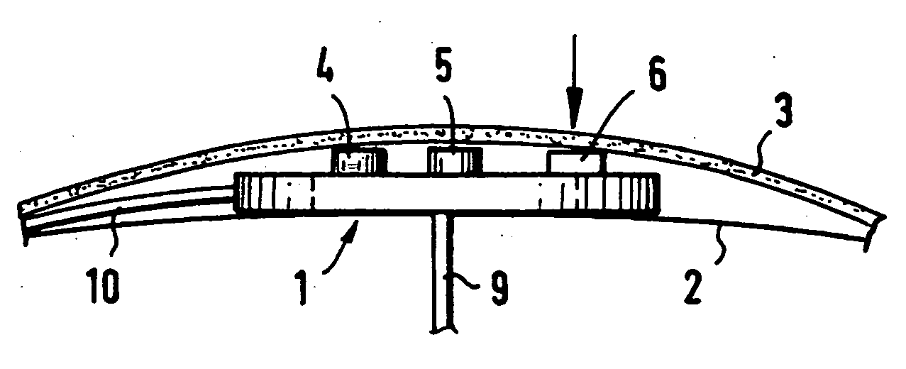
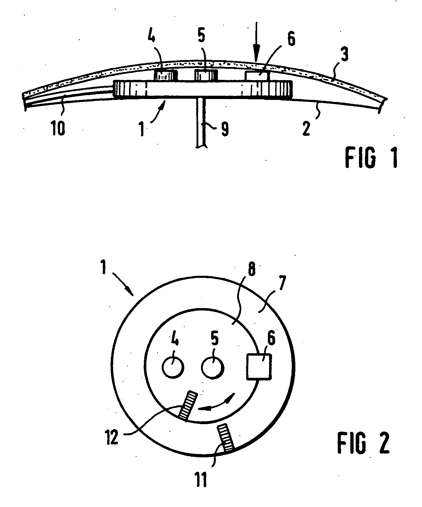
[0016] The illustrated fluid valve 1 is secured to the skull bone 2 under the scalp 3, so that the adjustment pushbuttons 4 and 5 as well as an unlocking pushbutton 6 can be actuated through the scalp 3. The unlocking pushbutton 6 serves for enabling the adjustment pushbuttons 4 and 5. The adjustment pushbuttons 4 and 5 can cause an adjustment of the valve body parts 7 and 8 that are rotatable relative to one another only when the unlocking pushbutton 6 also is pressed. The pushbuttons 4 and 5 respectively serve for opening and for closing the valve. The inner valve part 8 turns one step in the one or other direction relative to the outer part 7 each time a pushbutton 4 or 5 is pressed. Hose connection conduits 9 and 10 allow the inventive fluid valve to be inserted into the fluid system of the patient, so that a discharge of the fluid supplied to the fluid valve 1 at 9 ensues via the drain hose conduit 10.

[0017] In order to be able to recognize the setting of the fluid valve from ...


PUM


Abstract

An implantable fluid valve for the adjustable limitation of the fluid pressure in the brain of a patient has all valve component parts composed of non-magnetic material, thereby making the valve MR-compatible.

Description

BACKGROUND OF THE INVENTION RELATED APPLICATION [0001] The present application is a division of U.S. application Ser. No. 10 / 126,045, filed Apr. 9, 2002.FIELD OF THE INVENTION [0002] The present invention is directed to an implantable fluid valve for the adjustable limitation of the fluid pressure in the brain of a patient. DESCRIPTION OF THE PRIOR ART [0003] Valves that allow a setting of the maximum pressure from the outside of a patient, and automatically allow fluid to flow off given excess pressure, are required for patients whose discharge of fluid from the brain is abnormal. [0004] Valves that can be set from the outside by means of magnetic forces are commercially available. These valves are not MR-compatible. (As used herein, MR stands for magnetic resonance.) Examination of the patient in conventional MR scanners thus is not possible without risk, particularly given flux densities of 1 T and above. A maladjustment of the programmed pressure level or even damage to the impl...

Claims


Application Information

Patent Timeline
Patent Type & Authority Applications(United States)
IPC IPC(8): A61F2/04A61M27/00
CPCA61M27/006
Inventor KUTH, RAINERRUPPRECHT, THOMAS
Owner SIEMENS AG
Why Eureka
Try Eureka