Ball catching tool for baseball or softball

a technology for baseball or softball, applied in the field of baseball or softball catching tools, can solve the problems of limited small degree of freedom in selecting the height of slip preventing means, and failure to catch balls

Inactive Publication Date: 2006-09-14
MIZUNO CORPORATION
View PDF10 Cites 9 Cited by
  • Summary
  • Abstract
  • Description
  • Claims
  • Application Information

AI Technical Summary

Benefits of technology

[0010] The present invention was made to solve the above-described problem, and its object is to provide a ball catching tool that can reduce b

Problems solved by technology

As the slip preventing means is formed by mold pressing of the surface skin, the height of the slip preventing means is limited.
Further, as the surface of the slip preventing means is the surface skin, degree of freedom in selecting the height of the slip preventing means is small.
The embossed pattern of small dots is formed by mold pressing, and therefore, its height is limited.
Among ball catching failures, a so-called fumble occurs due to insufficient closing of the ball catching tool by th

Method used


Image

  • Ball catching tool for baseball or softball
  • Ball catching tool for baseball or softball
  • Ball catching tool for baseball or softball

Examples


embodiment 1

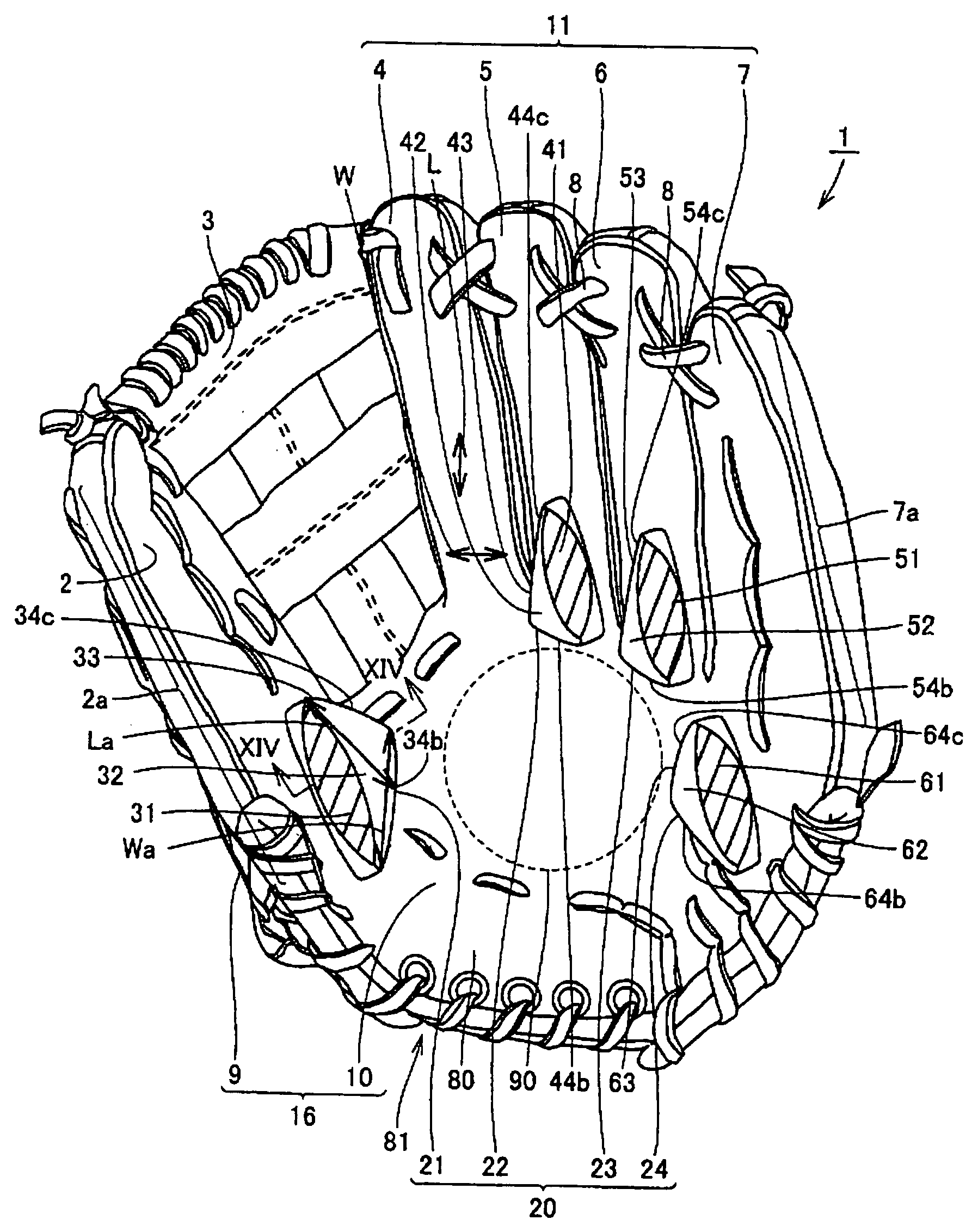
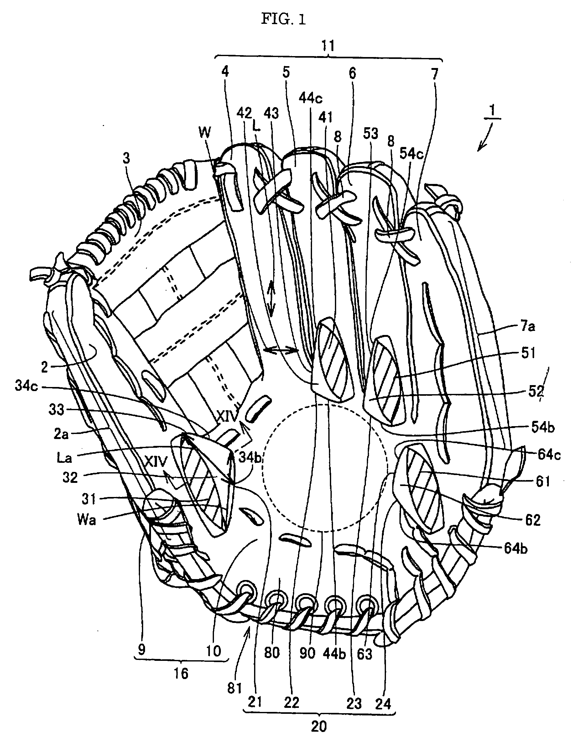
[0113]FIG. 1 is a front view of a ball catching tool 1 in accordance with Embodiment 1. As shown in FIG. 1, ball catching tool 1 includes a thumb-stall 2 receiving the thumb of a user, a web portion 3, and finger-stalls 11 receiving fingers of the user other than the thumb. The finger-stalls 11 include an index-finger-stall 4 receiving the index finger of the user, a middle-finger-stall 5 receiving the middle finger of the user, a ring-finger-stall 6 receiving the ring finger of the user, and a little-finger-stall 7 receiving the little finger of the user. At the central portion of ball catching tool 1, a pocket portion 90 and ball catching assisting portion 20 are provided, for receiving a hardball for baseball, rubber ball or softball (hereinafter simply referred to as a ball, to refer to any of the rubber ball, hardball and softball).

[0114] Generally, a hardball refers to a ball including a small core of cork, rubber or similar material, strings wound therearound and two pieces ...

embodiment 2

[0268] Embodiment 2 of the present invention will be described with reference to FIG. 29. FIG. 29 is a front view of a ball catching tool 100 in accordance with Embodiment 2, and as can be seen from FIG. 29, on a surface of ball catching surface skin 10 of ball catching tool 100, ball catching assisting portion 21 for the thumb is arranged near the root portion of thumb-stall 2, and at root portions of finger-stalls, bulged portions 120 are formed. Bulged portions 120 include bulged portions 122, 123 and 124 for the middle finger, ring finger and little finger arranged at the root portions of middle-finger-stall 5, ring-finger-stall 6 and little-finger-stall 7, respectively.

[0269] Bulged portions 122, 123 and 124 for the middle finger, ring finger and little finger are all formed such that the front surface of ball catching surface skin 10 bulges outward. Further, sponge or the like is filled in each of bulged portions 122, 123 and 124 for the middle finger, ring finger and little ...

embodiment 3

[0278] Referring to FIG. 30, Embodiment 3 of the present invention will be described. FIG. 30 is a front view of a ball catching tool 200 in accordance with Embodiment 3, and as can be seen from FIG. 30, ball catching tool 200 includes ball catching assisting portion 21 for the thumb and bulged portion 220. Bulged portion 220 includes a bulged portion 222 for the middle and ring fingers, and a bulged portion 223 for the little finger. Bulged portion 222 for the middle and ring fingers includes an extending portion 222a extending from the root portion to the tip end portion of middle-finger-stall 5, and a bent portion 222b. Bent portion 222b is bent at the root portion of extending portion 222a toward the side surface 7a of little-finger-stall 7, and arranged along the root portions of middle-finger-stall 5 and ring-finger-stall 6. Therefore, bulged portion 222 for the middle and ring fingers is formed to serve both as bulged portion for the middle finger and bulged portion for the r...


PUM


Abstract

A ball catching tool for baseball or softball includes a thumb-stall receiving the thumb, an index-finger-stall receiving the index finger, a middle-finger-stall receiving the middle finger, a ring-finger-stall receiving the ring finger and a little-finger-stall receiving the little finger; wherein a ball catching assisting portion of at least 6.15 mm and at most 26.6 mm in height is provided on a ball catching side surface of the thumb-stall or its root portion.

Description

[0001] This nonprovisional application is based on Japanese Patent Applications Nos. 2005-025156 and 2006-008992 filed with the Japan Patent Office on Feb. 1, 2005 and Jan. 17, 2006, respectively, the entire contents of which are hereby incorporated by reference. BACKGROUND OF THE INVENTION [0002] 1. Field of the Invention [0003] The present invention relates to a baseball or softball catching tool (hereinafter simply referred to as a “ball catching tool”) and, more specifically, to a catching tool having a protruded portion on a surface thereof, to prevent unexpected slipping of the ball. [0004] 2. Description of the Background Art [0005] Baseball or softball gloves as examples of conventional ball catching tool are described in Japanese Utility Model Laying-Open Nos. 57-29274, 57-29275, 56-90274 and 56-171079. [0006] Japanese Utility Model Laying-Open No. 57-29274 describes a glove with a plurality of slip preventing means in the form of protrusions surrounding the central portion...

Claims


Application Information

Patent Timeline
IPC IPC(8): A41D13/08
CPCA63B71/143
Inventor TSUKAMOTO, MICHIHARUKOGAWA, DAISUKEITO, NORIFUMIKATO, KEI
Owner MIZUNO CORPORATION
Why Eureka
Try Eureka