
Hair trimmer

a technology of hair trimmer and rotating blade, which is applied in the direction of metal working apparatus, etc., can solve the problems of increasing the cutting pressure applied between the rotating blade and the cooperating stationary shell, and achieve the effect of increasing the contact pressure and increasing the cutting pressur

Inactive Publication Date: 2006-09-14
C C & L COMPANY
View PDF28 Cites 4 Cited by
  • Summary
  • Abstract
  • Description
  • Claims
  • Application Information

AI Technical Summary

Benefits of technology

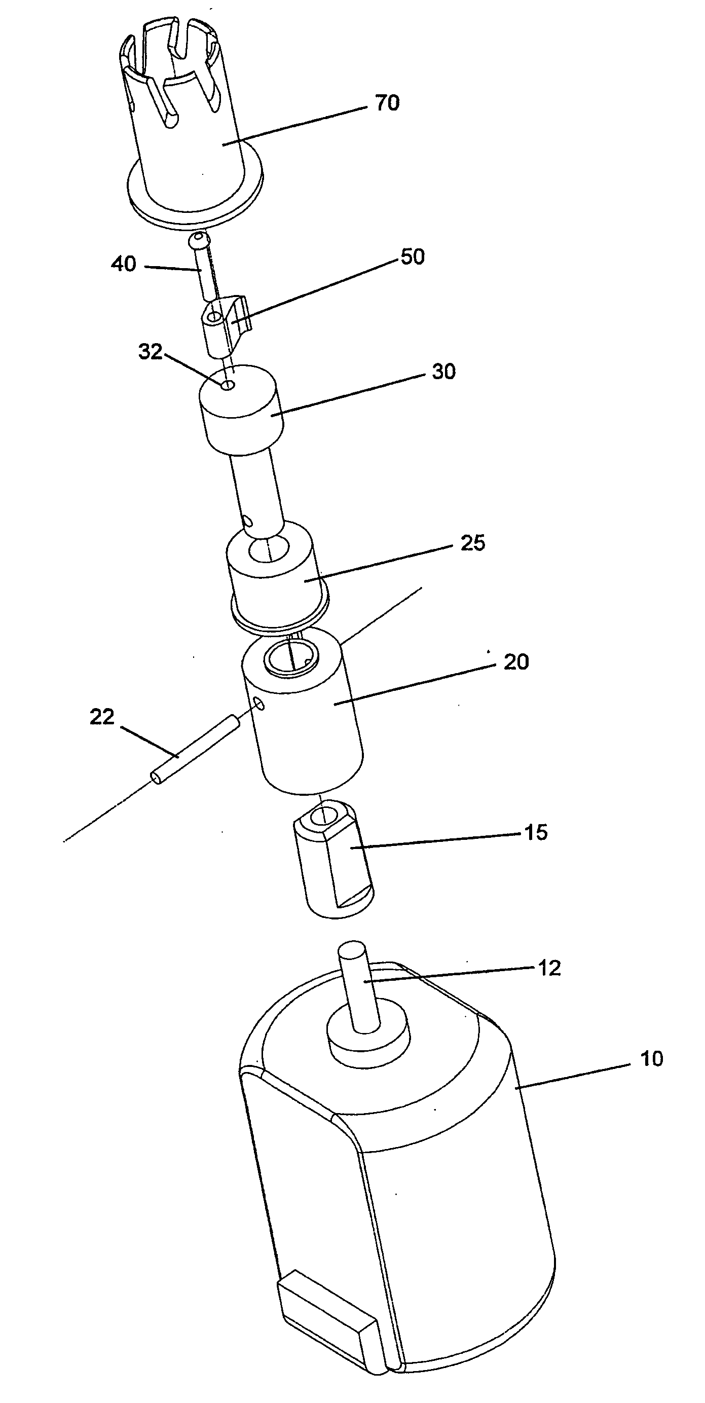
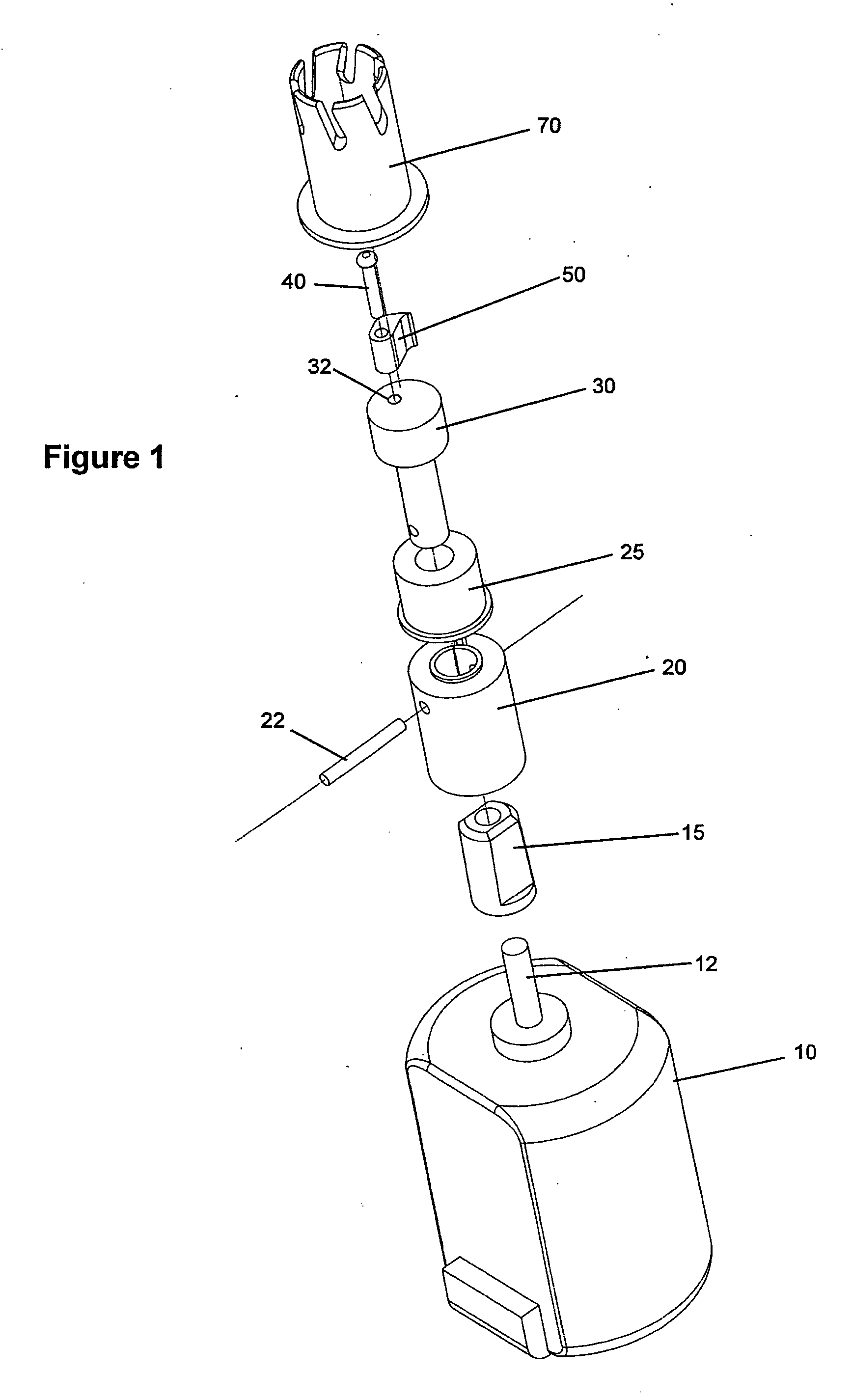
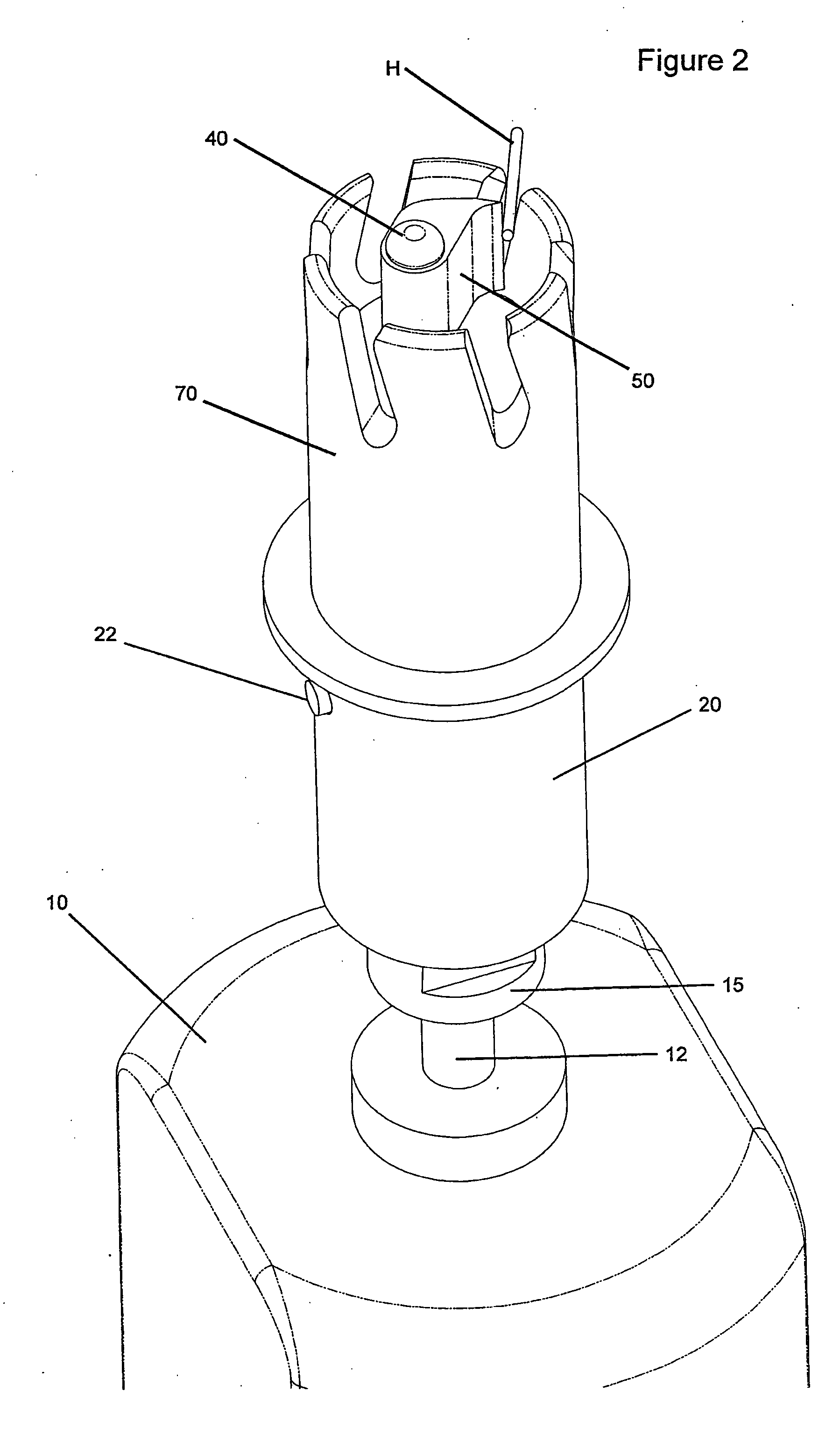
[0008] The shell, movable blade hinge and movable blade are positioned such that the cutting edge of the blade travels close to or along a portion of the interior surface of the shell and precedes the hinge such that resistance to the movement of the blade edge, such as that provided by a hair contacting the blade edge, will tend to wedge the blade more tightly between the hinge and the shell thereby increasing the contact pressure between the movable blade and the stationary surface.
[0010] Various embodiments of the present invention utilize one or more blades hingedly connected to a movable blade hinge. As used herein, the term “hinge” and its various forms are used to indicate that the position of the cutting edge of the movable blade is not fixed relative to the movable blade support. As described in further detail below, the movable blade support can be fairly described as a hinge support, including but not limited to a movable shaft on which the movable blade is freely rotatable. The hinge connection between one or more movable blades and the respective blade supports can be mechanical and / or can take the form of a living hinge which relies upon the flexibility and / or resiliency of material used to manufacture one or more of the elements of the device, such as the movable blade support or the movable blade.

Problems solved by technology

This results in an increased cutting pressure applied between the rotating blade and the cooperating stationary shell caused by a wedging action of the rotating blade into the hair or whiskers being cut.

Method used


Image

  • Hair trimmer
  • Hair trimmer
  • Hair trimmer

Examples


Embodiment Construction

[0019] Various embodiments of the present invention are directed to hair cutters comprising at least one movable blade connected to a movable blade support. The devices of the present invention also comprise a stationary blade which can be in the form of a shell within which the movable blade is moved. For purposes of cutting hair it is important that there is relative movement between the cutting edge of the movable blade and the stationary blade. While in the preferred embodiments described herein, the “stationary” surface is actually stationary relative to the hand of the person shaving or a housing on the motor, according to other embodiments the surface and / or cutting edges which cooperate with the movable blade can be movable either in a direction opposite to movement of the movable blade or in the same direction but at a slower rate. Therefore, as used herein, the term “stationary blade” is used to indicate a surface comprising at least one edge which is relatively movable to...


PUM


Abstract

Hair trimmers, for example hair trimmers particularly suited for trimming nose hair. One aspect includes at least one movable blade and at least one shell having an interior surfaces at least one hole extending through the shell, and an interior cutting edge. The movable blade is hingedly connected to a movable blade hinge comprising a longitudinal axis. The shell, movable blade hinge and movable blade are positioned such that the cutting edge of the blade travels close to or along a portion of the interior surface of the shell and precedes the hinge such that resistance to the movement of the blade edge, such as that provided by a hair contacting the blade edge, will tend to wedge the blade more tightly between the hinge and the shell thereby increasing the contact pressure between the movable blade and the stationary surface. The cutting edge can also be urged toward the interior surface by centrifugal force.

Description

RELATED APPLICATION DATA [0001] This application claims the benefit of related U.S. Provisional Patent Application Ser. No. 60 / 661,645 filed on Mar. 14, 2005.[0002] The present invention is directed to a hair trimmer and is particularly suited for use as a nose hair trimmer. BACKGROUND [0003] Various devices have been previously disclosed for trimming hair including, for example, nose hair trimmers. Previously disclosed nose hair trimmers include devices having one or more openings through which hairs can extend into an area where they are cut. Some previous devices include movable blades driven by rotary motors which act in cooperation with stationary surfaces defining cutting areas to cut hair extending into the cutting areas. Those skilled in the art will appreciate that as movable blades are used for cutting, their cutting edges will tend to become dull over time due to the contact between the cutting edge of the movable blade relative to a static cutter. Some prior art devices ...

Claims


Application Information

Patent Timeline
Patent Type & Authority Applications(United States)
IPC IPC(8): B26B19/00
CPCB26B19/148
Inventor CHAN, SIK-LEUNG
Owner C C & L COMPANY
Learn More