Inductive powering surface for powering portable devices

a powering surface and portable technology, applied in the field of portable devices, can solve the problems of heavy power supply, device movement, device power operation, etc., and achieve the effect of significantly reducing the cost of the powering devi

Inactive Publication Date: 2006-09-14
MICROSOFT TECH LICENSING LLC
View PDF6 Cites 492 Cited by
  • Summary
  • Abstract
  • Description
  • Claims
  • Application Information

AI Technical Summary

Benefits of technology

[0007] In accordance with another aspect of the invention, the primary coils in the inductive powering surface are arranged into a matrix with rows and columns, with the coils in each row or column switchably connected to a drive circuit. To energize a selected primary coil, the row and column of that coil are switched on. This arrangement allows the cost of the powering device to be significantly reduced as compared to the prior art, because the number of switchable drive circuits required is proportional to the linear dimensions of the powering surface, instead of its area.

Problems solved by technology

Nevertheless, one major technical obstacle that has been hindering the mobility of portable devices is that those devices need power to operate, and replenishing the power typically requires the use of a power cord.
Such a power supply is bulky and heavy, and may be unusable when the user travels to a region with a different AC voltage standard.
A frustrating scenario frequently experienced by users of portable devices is that the portable device runs out of power and its external power supply or charger is unavailable or unusable, rendering the portable device useless.
One fundamental problem with this arrangement is that the oscillator circuit of the secondary coil requires power to operate.
If the battery of the portable device is completely drained, there is no power available to operate the oscillator circuit.
As a result, the portable device cannot be recharged, since the desk-type power station cannot sense its presence and thus will not energize the primary coils to transfer power to it.
Another problem with this arrangement is that the number of drive circuits for the primary coils is proportional to area of the desk surface, and the cost for the drive circuits can be quite high for a large desk surface.

Method used


Image

  • Inductive powering surface for powering portable devices
  • Inductive powering surface for powering portable devices
  • Inductive powering surface for powering portable devices

Examples


Embodiment Construction

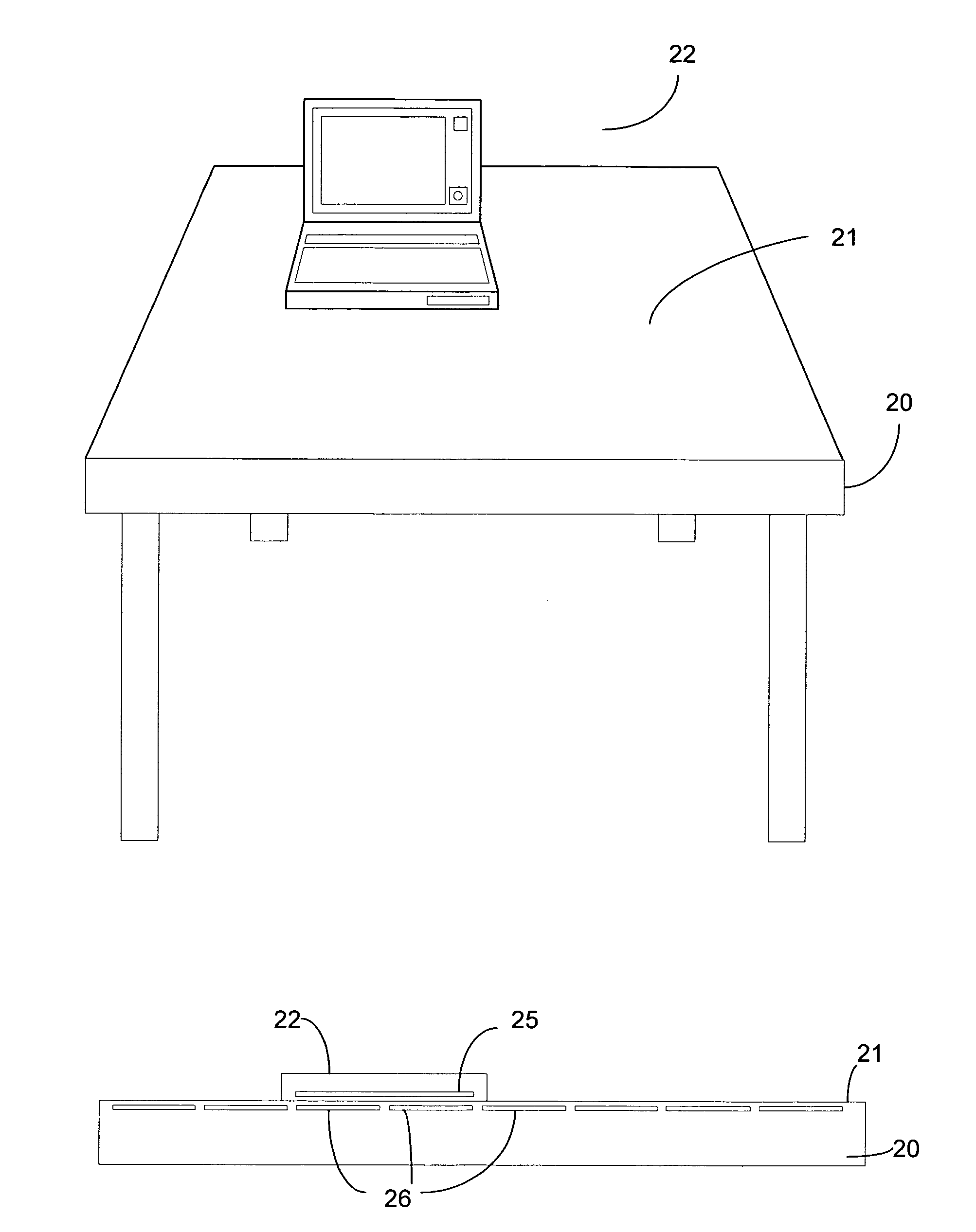
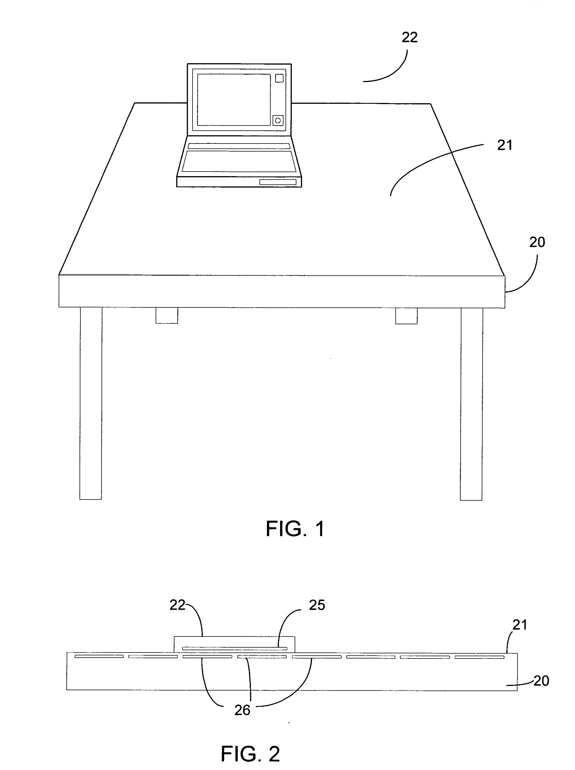
[0018] Turning to the drawings, wherein like reference numerals refer to like elements, the invention provides a powering device 20 with an inductive powering surface 21 for powering a portable device placed on the surface. The powering device 20 may be in the form of, for example, a computer desk, a conference table, a night stand, or a powering pad, etc. There are no particular limitations on the shape and form of the powering device. A significant advantage of using the inductive powering surface 21 to transfer power to a portable device 22 is that no electrical contact or connection has to be made to power the portable device. This can provide significant convenience to users of portable devices. For example, if the powering device 20 is a conference table, users participating in a meeting only have to place their laptop computers or tablet PC's on the surface of the table, and their portable devices will be automatically powered or recharged by the table surface. As a result, t...


PUM


Abstract

An inductive powering device provides power to a portable device via inductive coupling between primary coils in the surface of the powering device and a secondary coil in the portable device. The portable device includes a passive locator device, such as an RFID device, to allow the primary coils of the inductive powering surface to detect the presence and location of the secondary coil, and only primary coils adjacent the secondary coil are energized for power transfer. A cost-effective driving configuration that arranges the primary coils into a matrix with drive circuits switchably connected to the row and columns is used to energize the primary coils.

Description

RELATED APPLICATION [0001] This application claims the priority of U.S. Provisional Application 60 / 660,524, filed on Mar. 10, 2005.TECHNICAL FIELD [0002] This invention relates generally to portable devices such as laptop computers, tablet PC's, PDA's, etc., and more particularly to a device that utilizes an inductive power transfer mechanism to power portable devices. BACKGROUND OF THE INVENTION [0003] Portable computing devices such as laptop computers, tablet PC's, email accessing devices, PDA's, etc. are becoming increasing popular and have become indispensable tools for many users. With the advancements in computer and network technologies, the portable devices are more and more powerful and versatile, and a great emphasis in computer hardware development is placed on further enhancing the mobility of such devices. Nevertheless, one major technical obstacle that has been hindering the mobility of portable devices is that those devices need power to operate, and replenishing the...

Claims


Application Information

Patent Timeline
Patent Type & Authority Applications(United States)
IPC IPC(8): H02J7/04
CPCH02J5/005H02J7/025H02J7/0042H02J50/402H02J50/80H02J50/90H02J50/70H02J50/10
Inventor HSU, FENG-HSIUNG
Owner MICROSOFT TECH LICENSING LLC
Why Eureka
Try Eureka