Alertness monitor

a technology of alertness monitor and monitor, which is applied in the field of alertness monitor, can solve the problems of many people being unaware of their drowsiness, affecting the ability of operators, and unable to solve the problem of drowsiness driving

Inactive Publication Date: 2006-09-14
SDIP HLDG
View PDF16 Cites 23 Cited by
  • Summary
  • Abstract
  • Description
  • Claims
  • Application Information

AI Technical Summary

Benefits of technology

[0022] It is a benefit of this invention that the monitor can continuously record the operators alertness based on a scale developed by testing sleep deprived subjects. Many countries have legislated that it is illegal to drive a vehicle or have control of machinery etc with a blood alcohol level above specified values. This invention enables drowsy operators to be judged in a similar manner and provide a measure of legal fitness to operate a vehicle or machinery.
[0023] The method of this invention can be implemented using any suitable eye movement monitoring devices. Cameras may be used to continuously monitor eye and eyelid movements. However reflected light beams also provide data relevant to these movements. For suitability in a range of background light environments from dark to bright sunlight infra red light beams have proved to be effective.

Problems solved by technology

The detection of drowsiness is of importance because drowsiness impairs the ability of operators of a wide range of equipment including motor vehicles, aircraft and boats as well as industrial equipment.
The problem of drowsy driving cannot be solved by educating drivers to take remedial action when feeling drowsy.
The difficulty is that many people are unaware of their drowsiness before and during the drowsiness even though they may be alert and aware after they rouse.
This means one cannot predict when their level of drowsiness will next decrease to the point of danger because the drowsy state involves a loss of awareness of the present; an involuntary lapse of attention.
All of the above approaches fail to provide a real time alertness monitor that can provide a calibrated measure of the operator's alertness.

Method used


Image

  • Alertness monitor
  • Alertness monitor
  • Alertness monitor

Examples


Embodiment Construction

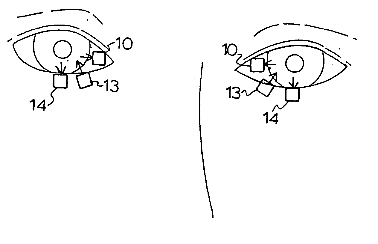
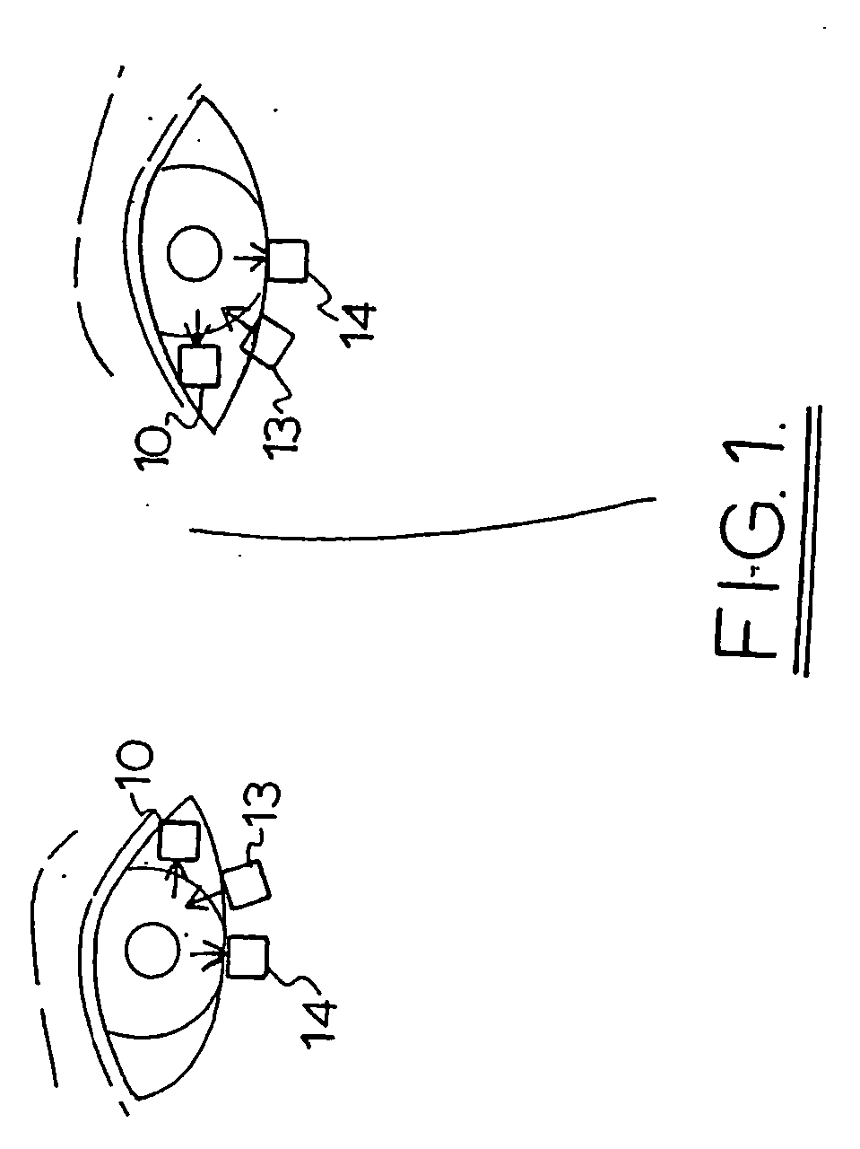
[0036]FIG. 1 is a schematic diagram showing the location of the emitters and detectors

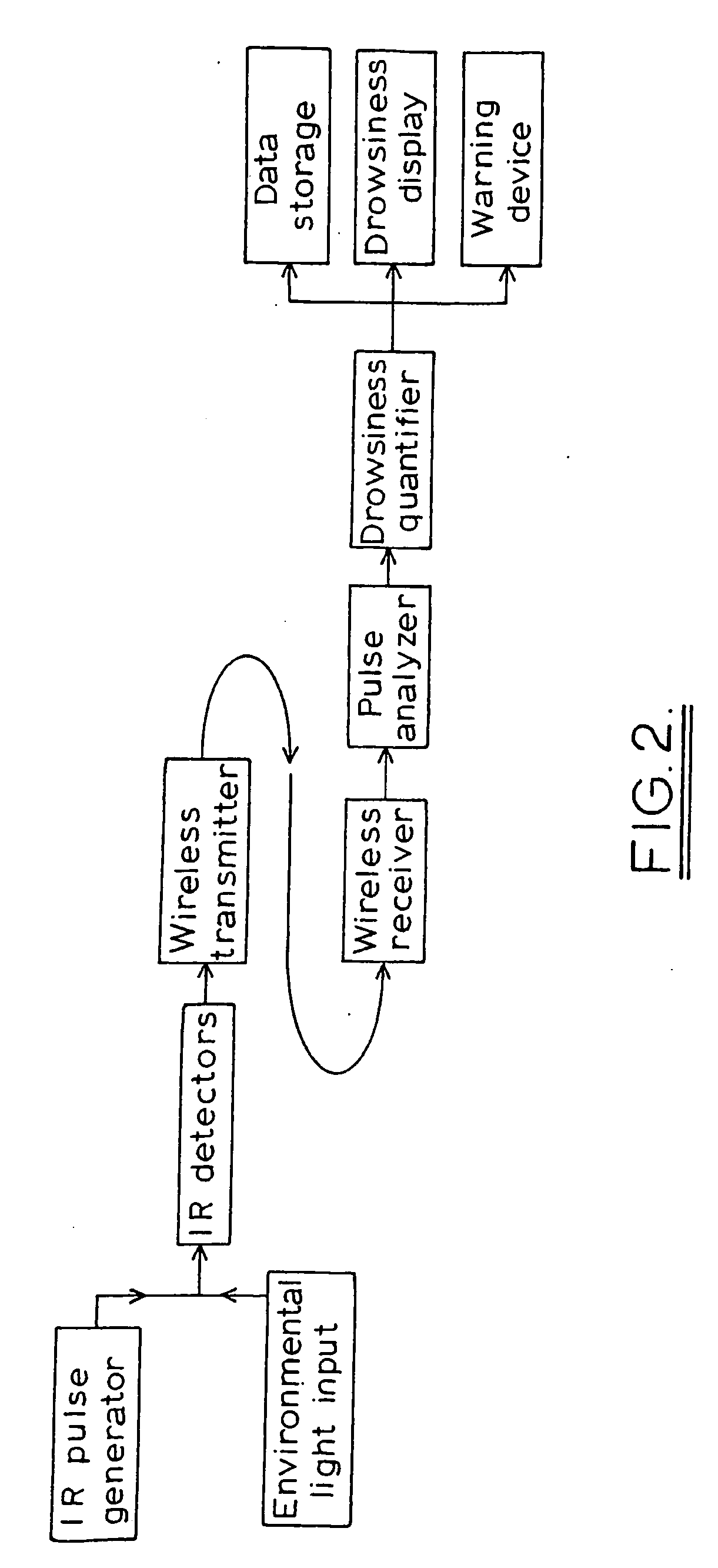
[0037]FIG. 2 is a schematic layout of the system function according to this invention;

[0038]FIG. 3 is an example of a graphical output of this invention relating to eye lid movement;

[0039]FIG. 4 is an example of a graphical output of this invention relating to eye movement for the left and right eyes;

[0040]FIG. 5 illustrates a graph used to determine the blink amplitude velocity ratio (BAVR);

[0041]FIG. 6 illustrates a graph used to determine the saccade amplitude velocity ratio (SAVR);

[0042]FIG. 7 illustrates the difference between the opening and closing velocity of blinks;

[0043]FIG. 8 illustrates the signal from a slow, partial blink of a sleep deprived subject;

[0044]FIG. 9 illustrates the BAVR per minute plotted during a 10 minute performance test done repeatedly during sleep deprivation over night;

[0045]FIG. 10 illustrates the relationship between mean BAVR and blood alcohol concentrat...


PUM


Abstract

An alertness monitoring system uses reflectance measurement of infrared light pulses to monitor eye movement of a vehicle or machine operator. The data is used to measure eye and eyelid movement for presence slow or drifting eye movements, and / or eyelid closure and optionally one or more of, absence of saccadic movement, loss of eye co-ordination, wavering eyelids, partial eye closure, and drooping eyelids as indicators of loss of attention and drowsiness. The eye movements of a subject are analysed using reflected infra red light to obtain measures of the blink amplitude velocity ratio and the saccade amplitude velocity ratio. The readings are continuously compared with eye movement data indicative of degrees of alertness so that the monitor provides an indication of the operator's fitness to operate the vehicle or machine from the point of view of drowsiness no matter how it is caused.

Description

[0001] This application is a Continuation Application of U.S. application Ser. No. 10 / 488,960 filed Mar. 9, 2004 (allowed) and for which priority is claimed under 35 U.S.C. § 120. application Ser. No. 10 / 488,960 is the national phase of PCT International Application No. PCT / AU02 / 01508 filed Nov. 7, 2002 under 35 U.S.C. § 371. This application also claims priority of Application No. PR 8723 filed in Australia on Nov. 8, 2001 under 35 U.S.C. § 119. The entire contents of each of the above-identified applications are hereby fully incorporated by reference. [0002] This invention relates to a method and device for testing alertness and the onset of drowsiness by monitoring eye and eyelid movement.BACKGROUND TO THE INVENTION [0003] The detection of drowsiness is of importance because drowsiness impairs the ability of operators of a wide range of equipment including motor vehicles, aircraft and boats as well as industrial equipment. The problem of drowsy driving cannot be solved by educati...

Claims


Application Information

Patent Timeline
Patent Type & Authority Applications(United States)
IPC IPC(8): G08B23/00A61B3/113A61B5/18G08B21/06G08G1/16
CPCA61B3/113A61B5/18G08B21/06A61B5/163G06V40/19G06V20/597
Inventor JOHNS, MURRAY
Owner SDIP HLDG
Why Eureka
Try Eureka