Control parameters for optimizing MEA performance

a technology of mea and control parameters, which is applied in the manufacturing process of electrodes, cell components, electrochemical generators, etc., can solve the problems of high manufacturing cost of mea, difficult cleaning step, and high cost of eptfe substrates

Inactive Publication Date: 2006-09-14
GM GLOBAL TECH OPERATIONS LLC
View PDF30 Cites 37 Cited by
  • Summary
  • Abstract
  • Description
  • Claims
  • Application Information

AI Technical Summary

Benefits of technology

[0015] In accordance with a first embodiment of the present invention, an electrode catalyst layer for use in a fuel cell is provided, comprising: (1) a catalyst portion; and (2) an ionomeric material disposed in the catalyst portion, wherein the co

Problems solved by technology

MEAs are relatively expensive to manufacture and require certain conditions for effective operation.
However, the ePTFE substrate is exp

Method used


Image

  • Control parameters for optimizing MEA performance
  • Control parameters for optimizing MEA performance
  • Control parameters for optimizing MEA performance

Examples


Embodiment Construction

[0053] The following description of the preferred embodiment(s) is merely exemplary in nature and is in no way intended to limit the invention, its application, or uses.

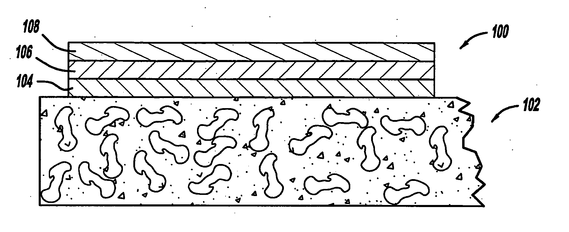
[0054] In accordance with the general teachings of the present invention, a gradient of ionomeric material is generated, disposed, or otherwise provided in the electrode, e.g., when bonded to the membrane. That is, a gradient exists with respect to the ionomeric material vis-à-vis the membrane. By way of a non-limiting example, the ionomer concentration, e.g., with respect to the carbon content of the catalyst layer (e.g., expressed as a ratio), is greatest in the area closest to the membrane (e.g., the membrane side) and is decreased in the area furthest from the membrane (e.g., the gas side). By way of another non-limiting example, the ionomer gradient can be formed such that the concentration (or the ratio if expressed in relation to the carbon content of the catalyst layer) can gradually, as opposed to rapidly, ...


PUM


Abstract

A gradient of ionomeric material is generated, disposed, or otherwise provided in an electrode suitable for use in a fuel cell. The ionomer concentration, e.g., with respect to the carbon content of the catalyst layer (e.g., expressed as a ratio), is greatest in the area closest to the membrane, e.g., of the fuel cell (e.g., the membrane side), and is decreased in the area furthest from the membrane (e.g., the gas side). By way of another non-limiting example, the ionomer gradient can be formed such that the concentration (or the ratio if expressed in relation to the carbon content of the catalyst layer) can gradually, as opposed to rapidly, decrease as the distance away from the membrane increases.

Description

CROSS-REFERENCE TO RELATED APPLICATION [0001] The instant application is a continuation-in-part of U.S. patent application Ser. No. 10 / 763,633, filed Jan. 22, 2004, the entire specification of which is expressly incorporated herein by reference.FIELD OF THE INVENTION [0002] The present invention relates generally to a membrane electrode assembly (MEA) for a proton exchange membrane fuel cell and, more particularly, to an MEA for a proton exchange membrane fuel cell, where the anode and / or cathode catalyst layers are formed on a porous and / or non-porous support wherein an ionomer material is incorporated therein in a gradient having a relatively high ionomer content closest to the membrane layer and a relatively low ionomer content layer furthest from the membrane layer. Additionally, the present invention relates to the formation of ionomer gradients in conjunction with catalyst coated diffusion media, wherein the catalyst coated diffusion media are hot pressed to a membrane, which ...

Claims


Application Information

Patent Timeline
IPC IPC(8): H01M4/86H01M4/96H01M4/94B05D5/12H01M4/88H01M8/10
CPCH01M4/0407H01M4/8642H01M4/881H01M4/8817H01M4/8825H01M4/8828H01M4/886H01M4/8882H01M2008/1095Y02E60/50Y02E60/10
Inventor YAN, SUSAN G.DOYLE, JOHN C.SOMPALLI, BHASKARGASTEIGER, HUBERT A.O'HARA, JEANETTE E.GU, WENBIN
Owner GM GLOBAL TECH OPERATIONS LLC
Why Eureka
Try Eureka