Knife with sliding blade and disengageable deployment mechanism

a technology of disengagement and deployment mechanism, which is applied in the field of knives, can solve the problems of affecting the normal movement of the user, the weight of the knife can attract the attention and concern of those around the user, and the disadvantages of the user's own

Active Publication Date: 2006-09-21
KAI US
View PDF47 Cites 24 Cited by
  • Summary
  • Abstract
  • Description
  • Claims
  • Application Information

AI Technical Summary

Benefits of technology

[0013] The body of the pin is oriented on the clip assembly such that, when the handle hangs from the pin, the second axis of the body is substantially p

Problems solved by technology

A knife of this size hanging from one's belt tends to interfere with normal movement, such as entering and exiting vehicles, sitting and bending, etc.
Additionally, a knife of this size can attract the attention and concern of those around the user.
While pocket knives do not suffer from the disadvantages inherent with belt knives, they do have disadvantages of their own.
For example, preparing to use a pocket knife is generally mor

Method used


Image

  • Knife with sliding blade and disengageable deployment mechanism
  • Knife with sliding blade and disengageable deployment mechanism
  • Knife with sliding blade and disengageable deployment mechanism

Examples


Embodiment Construction

[0025] In the following description, certain specific details are set forth in order to provide a thorough understanding of various embodiments of the invention. However, one skilled in the art will understand that the invention may be practiced without these details.

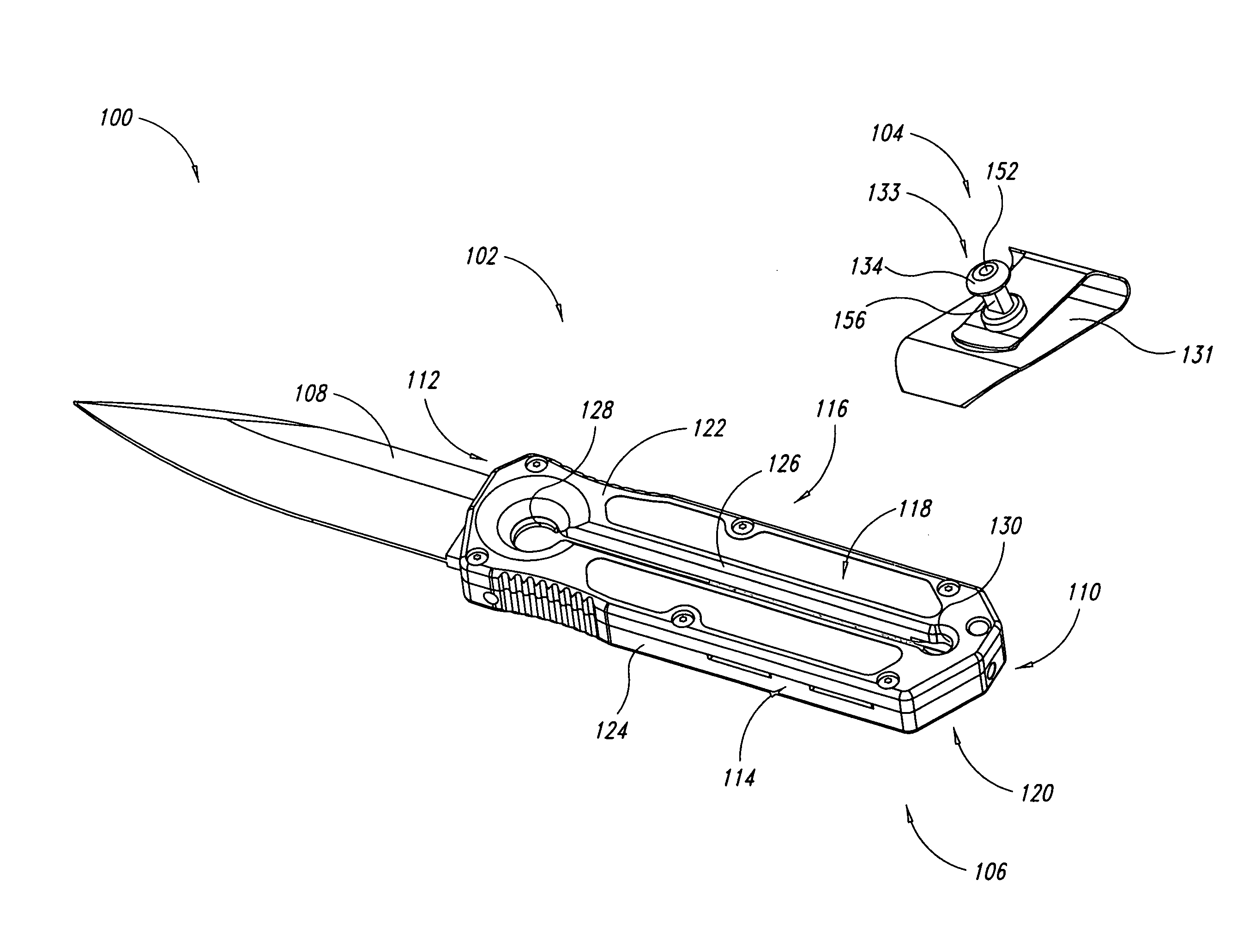
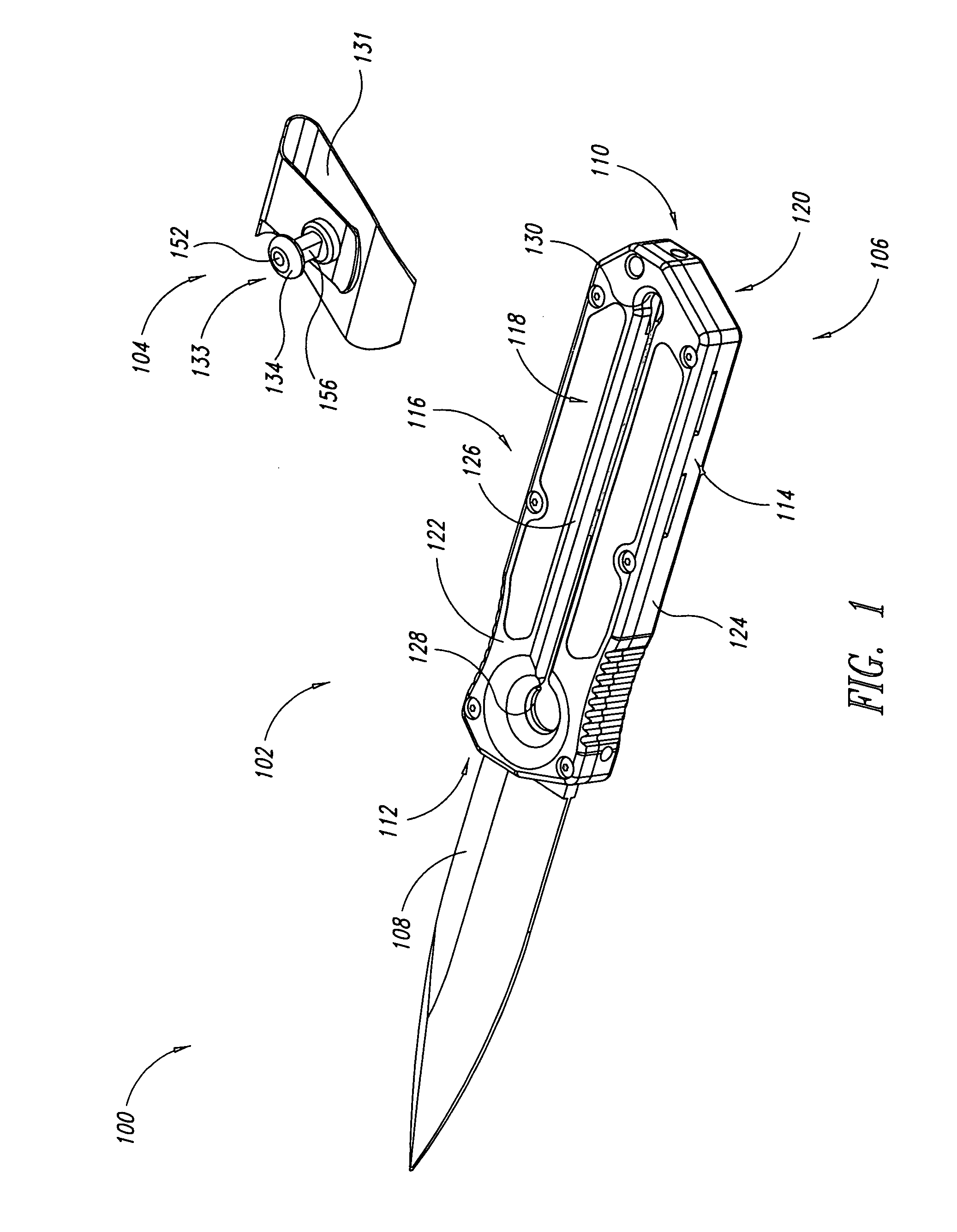
[0026]FIG. 1 shows a knife assembly 100 according to an embodiment of the invention. In describing components of the knife assembly 100, terms such as front, back, top, and bottom, may be used, as well as other terms to indicate direction, orientation, etc. such terms are for convenience only, in order to more clearly make reference to particular features. The scope of the present invention is not limited by such terms.

[0027] The knife assembly 100 includes a knife 102 and a clip assembly 104. The clip assembly 104 is configured to attach to a user's belt or the like, and to receive thereon the knife 102 for storage, as will be described in more detail hereafter.

[0028] The clip assembly 104 comprises a clip 131 and a...


PUM


Abstract

A knife assembly includes a handle having a blade cavity and a deployment slot extending longitudinally in the handle. A blade is slidably positioned within the blade cavity, and is slidable between a retracted position, in which the blade is wholly enclosed within the handle, and an extended position, in which a portion of the blade extends from a first end of the handle. A clip assembly includes a pin configured to releasably engage a tang portion of the blade in the blade cavity via the deployment slot. While the pin engages the blade, it can traverse the deployment slot from a first end to a second end to move the blade between the extended and retracted positions. The handle is configured to hang from the pin at the second end of the deployment slot while the blade is in the retracted position.

Description

CROSS-REFERENCE TO RELATED APPLICATION [0001] This application claims the benefit of German Patent Application No. 10 2005 014 706.2 filed Mar. 18, 2005, which application is incorporated herein by reference in its entirety. BACKGROUND OF THE INVENTION [0002] 1. Field of the Invention [0003] This invention relates to knives, and in particular, to a knife that is easy to deploy. [0004] 2. Description of the Related Art [0005] Knives have long been used to perform a variety of tasks, and knife designs have been adapted accordingly. While some knives are designed for extremely specialized applications, many people carry knives for general purpose use, and there is a significant demand for knives that are useful for a broad range of applications. Two categories of knives are fixed blade knives, and pocket knives. Fixed blade knives generally comprise a handle and a blade rigidly fixed together and configured to be received into a sheath or scabbard that may be attached to the user's bel...

Claims


Application Information

Patent Timeline
IPC IPC(8): B26B1/08
CPCB26B1/08B26B3/06
Inventor BEZOLD, URSGREEN, CRAIG
Owner KAI US
Why Eureka
Try Eureka