Auto chain tensioner
a chain tensioner and chain technology, applied in the direction of chain saws, metal sawing accessories, manufacturing tools, etc., can solve the problems of a lot of adjustment, and achieve the effect of facilitating the mounting of the chain to the guide bar
- Summary
- Abstract
- Description
- Claims
- Application Information
AI Technical Summary
Benefits of technology
Problems solved by technology
Method used
Image

Examples
first embodiment
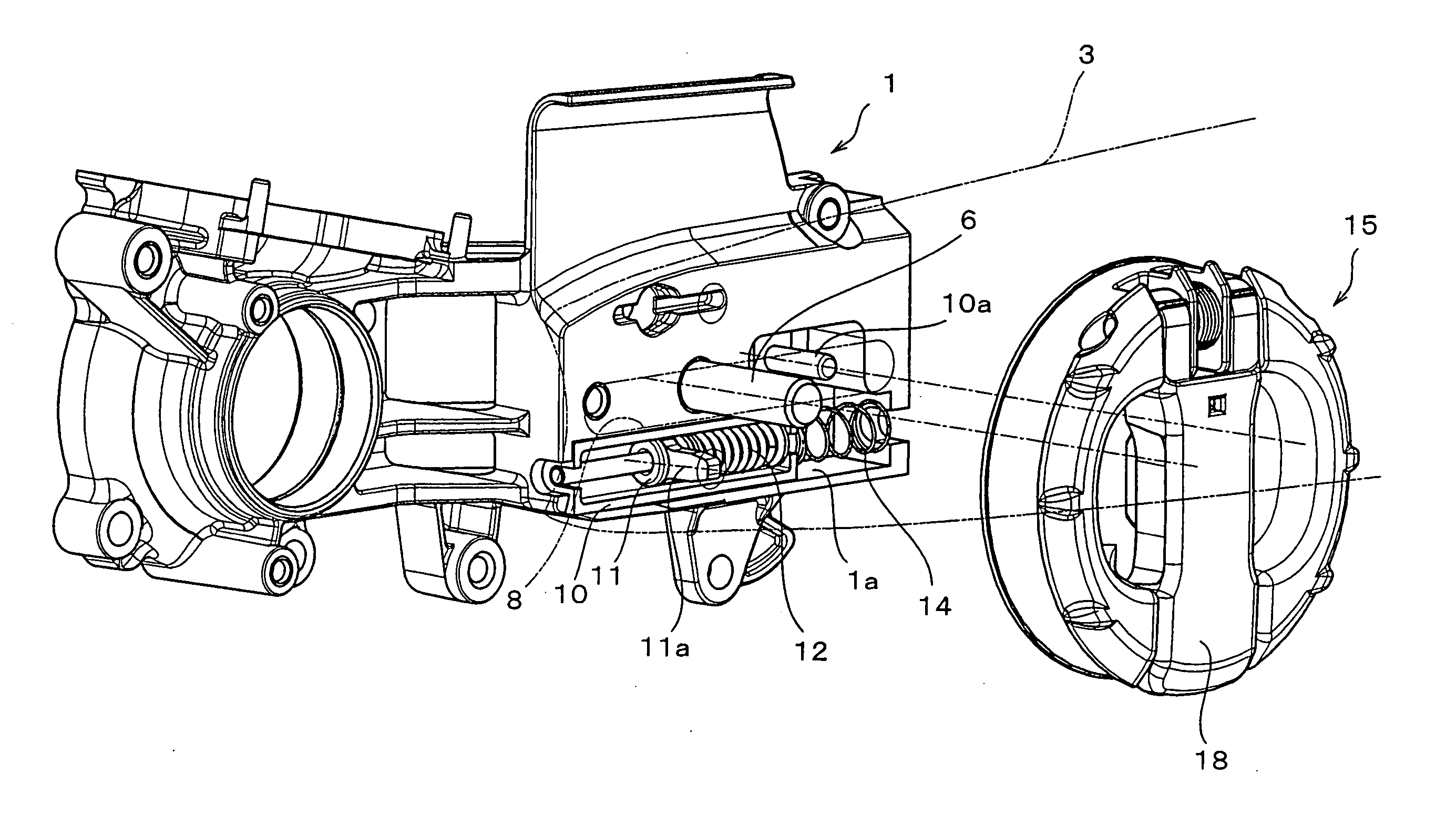
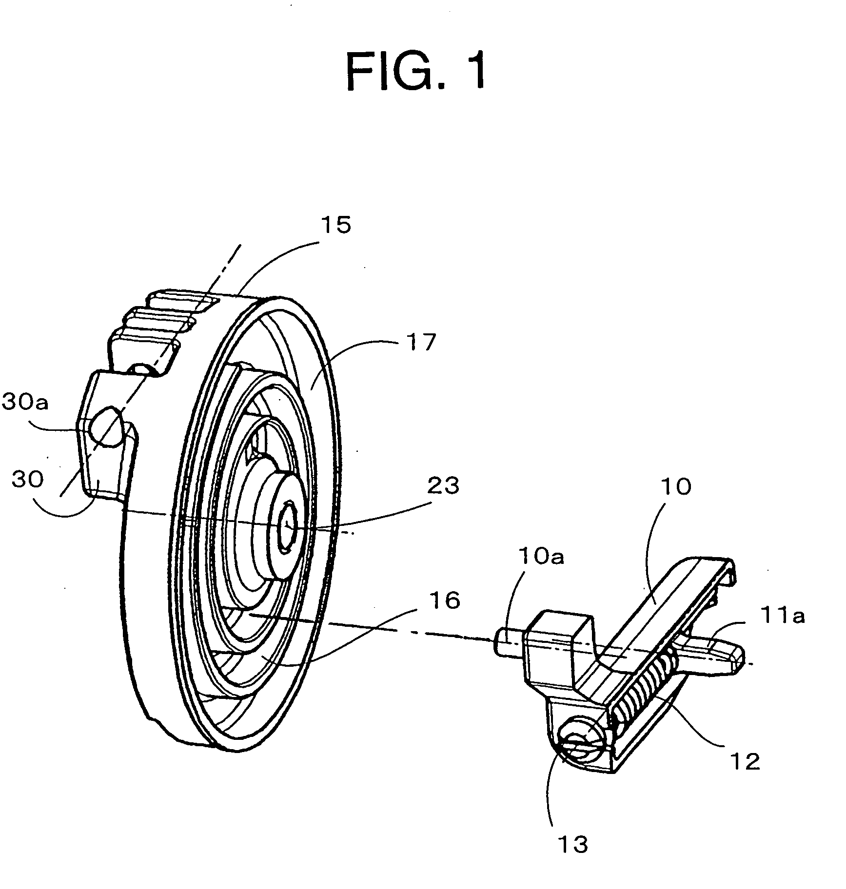
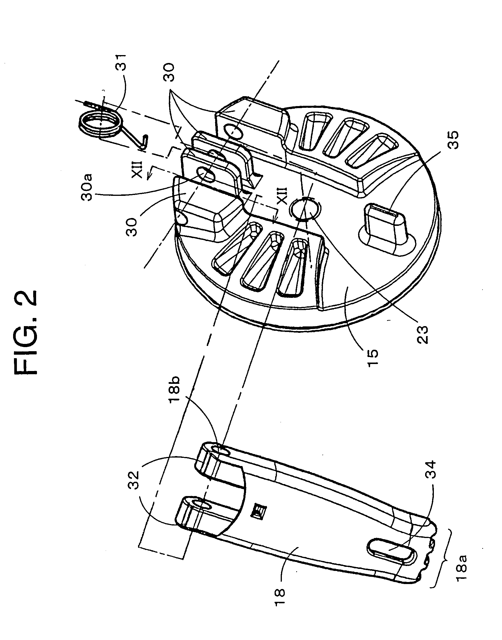
[0090]FIG. 1 is a perspective view seen from a rear side of a disk 15 after disassembling fixing means comprising the disk 15, a slider piece 10 and a tensioner 11 according to the invention. FIG. 2 is a perspective view seen from a front side of the disk 15 after disassembling the disk 15 and a lever 18. In FIG. 1, the lever 18 is omitted.
[0091]FIG. 3 is a plan view showing a slider piece 10 and tensioner 11 on a rear side of a chain cover 2. FIG. 4 shows the disk 15 and the lever 18 of the fixing means on a front side of the chain cover 2 and FIG. 5 shows a part of a sectional view taken along a line V-V in FIG. 4 without the lever 18. FIG. 6 is an outline view of a major portion of an engine cover 1 without the chain cover 2.
[0092] As shown in FIG. 6, a moving direction of a guide bar 3 is restricted by inserting a stud bolt 6 fixed in the engine cover 1 and an unshown guide pin into a guide slit 8 formed in the guide bar 3. Tension can be provided to a saw chain by hanging an u...
third embodiment
[0144] Next, a third embodiment is explained with reference to FIG. 19 wherein a link mechanism is used as means for a sliding of the slider piece 10, a fixing of the chain cover 2 and a fixing of the guide bar 3. Constructions of the slider piece 10 and the tensioner 11 are same as those in a case that the disk 15 is used as a fixing means and thus, same referential numerals are given to same members having same features as those in FIGS. 1 to 13, and thus descriptions thereof are omitted.
[0145] AS shown in FIG. 19, the slider piece 10 is slidably disposed in an unshown chain cover. Further, the slider piece 10 can be disposed via a return spring in the guide portion in the chain cover so as to return to the initial position easily when the chain cover is removed from the engine cover.
[0146] A link 41 is rotatably supported on the chain cover by a link axis portion 41a. A link 40 is rotatably supported on the slider piece 10 via a link axis portion 40a. These links 41 and 40 are r...
fourth embodiment
[0153]FIG. 20 shows the invention wherein the above-mentioned problem at a time of hanging the saw chain is solved and easy operation of hanging the saw chain is enabled. In this embodiment, as shown in FIG. 20, one or more permanent magnet piece 28 as an example of the temporary fixing means is fixed on the contact face of the engine cover 1 which contacts the guide bar. It is preferable to attach the permanent magnet piece 28 to the contact face of the engine cover 1 which contacts the guide bar in such a manner that an attaching face of the permanent magnet piece 28 and the contact face contacting the guide bar lie on a same plane. Furthermore, a magnetic attraction of the permanent magnet piece 28 is required to be strong enough to hold the guide bar 3. If the magnetic attraction is not sufficient, two or more permanent magnet piece 28 may be disposed on the contact face contacting the guide bar.
[0154] As aforementioned, by adopting an easy construction wherein the permanent mag...
PUM
| Property | Measurement | Unit |
|---|---|---|
| friction coefficient | aaaaa | aaaaa |
| friction coefficient | aaaaa | aaaaa |
| tension | aaaaa | aaaaa |
Abstract
Description
Claims
Application Information
 - Generate Ideas
- Intellectual Property
- Life Sciences
- Materials
- Tech Scout
- Unparalleled Data Quality
- Higher Quality Content
- 60% Fewer Hallucinations
Browse by: Latest US Patents, China's latest patents, Technical Efficacy Thesaurus, Application Domain, Technology Topic, Popular Technical Reports.
© 2025 PatSnap. All rights reserved.Legal|Privacy policy|Modern Slavery Act Transparency Statement|Sitemap|About US| Contact US: help@patsnap.com