Modular scroll sign display system

a scroll sign and module technology, applied in the direction of instruments, identification means, etc., to achieve the effect of lowering the cost and complexity of the overall display system, lowering the cost and complexity of the overall scroll sign, and facilitating the configuration of the scroll sign

Inactive Publication Date: 2006-09-21
SLUGGO LIGHTING
View PDF28 Cites 7 Cited by
  • Summary
  • Abstract
  • Description
  • Claims
  • Application Information

AI Technical Summary

Benefits of technology

[0038] Another aspect of the invention provides a control system for one or more scroll sign modules. The control system comprises a driving circuit having, for each scroll sign module and each corresponding pair of motors, a bi-directional switch capable of sourcing drive current to, and sinking drive current from, a common drive signal terminal which is shared by the pair of motors. The control system dispenses with the conventional H-bridge and half-bridge driver topologies, lowering the cost and complexity of the overall display system.
[0039] The control system may provide for minimal interconnect wiring between the control system and its associated scroll sign module(s), thereby further lowering the cost and complexity of the overall scroll sign and also easing scroll sign configuration, assembly, calibration and servicing.

Problems solved by technology

These deficiencies may relate to one or more of the above-identified characteristics and may also relate to other drawbacks associated with the particular prior art design.

Method used


Image

  • Modular scroll sign display system
  • Modular scroll sign display system
  • Modular scroll sign display system

Examples


Embodiment Construction

[0055] Throughout the following description, specific details are set forth in order to provide a more thorough understanding of the invention. However, the invention may be practiced without these particulars. In other instances, well known elements have not been shown or described in detail to avoid unnecessarily obscuring the invention. Accordingly, the specification and drawings are to be regarded in an illustrative, rather than a restrictive, sense.

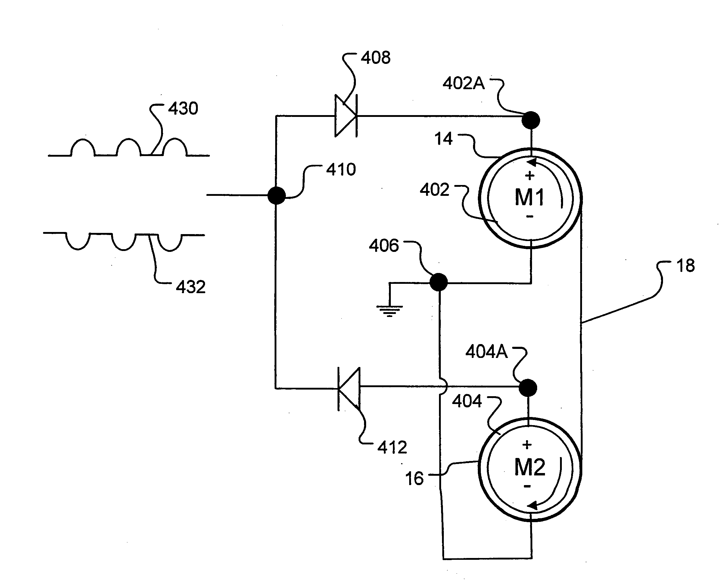
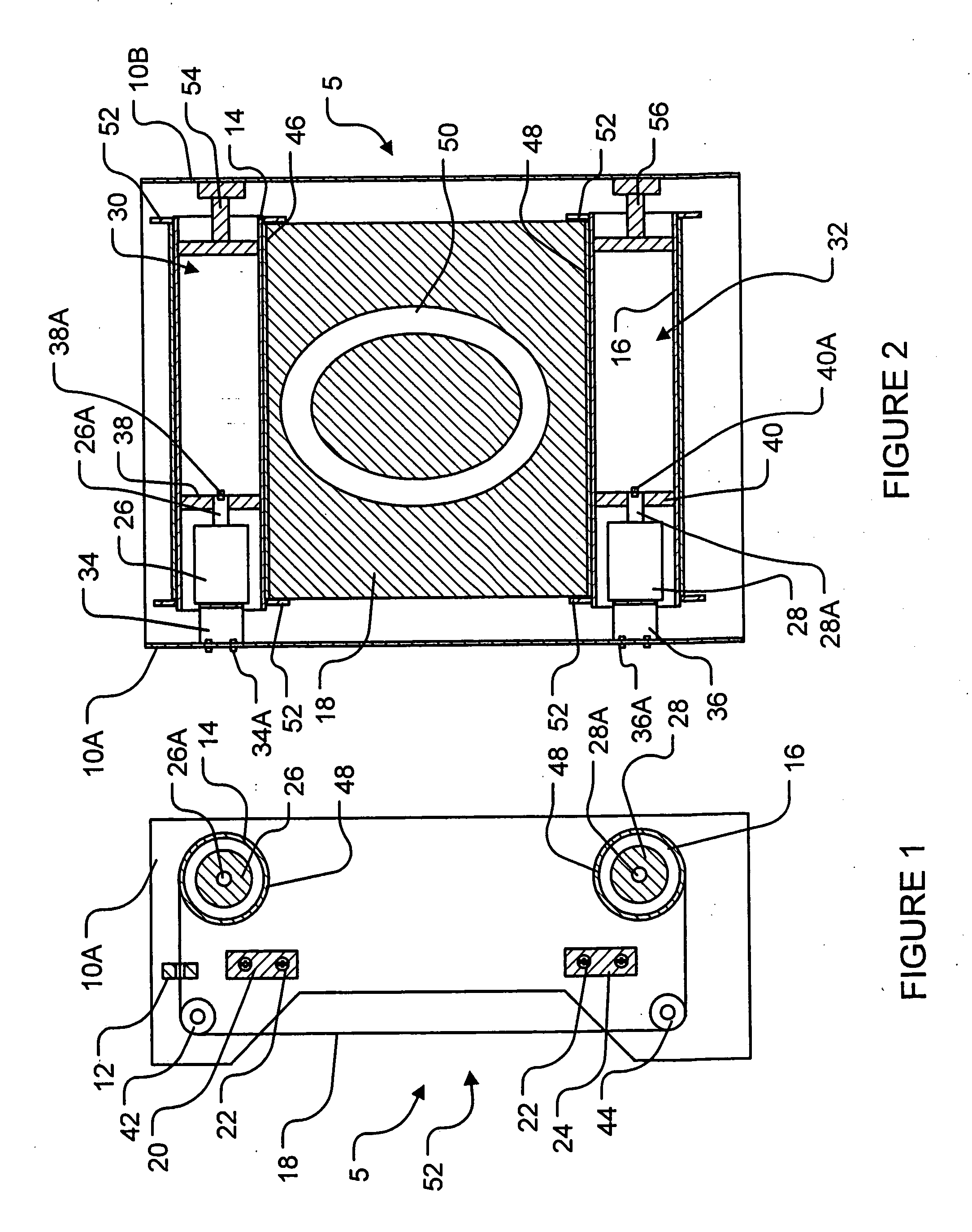
[0056]FIG. 1 and FIG. 2 respectively show partially cross-sectioned side and partially cross-sectioned rear views of a scroll sign module 5 according to a particular embodiment of the invention. Scroll sign module 5 comprises a pair of side frame members 10A, 10B, which are connected to one another via cross-rails 20, 24 and fasteners 22. Together, side frame members 10A, 10B and cross-rails 20, 24 provide a frame to which other components of scroll sign module 5 may be mounted.

[0057] Scroll sign module 5 comprises a pair of parall...


PUM


Abstract

One aspect of the invention provides scroll sign modules having laterally spaced-apart side frame members which support a pair of tape transport rolls therebetween. The axes of the rolls are parallel to each other. A tape, typically bearing visual indicia, extends between the two parallel rolls. A portion of the tape is wrapped around at least one of the rolls. Two controllable motors are mounted with at least a portion of each motor located in a bore of a corresponding one of the rolls. Each motor is operationally coupled to rotate its corresponding roll about its axis.

Description

RELATED APPLICATIONS [0001] This application claims the benefit of the 21 Mar. 2005 filing date of U.S. application No. 60 / 663,264 under 35 U.S.C. § 119(e) and the 21 Mar. 2005 filing date of Canadian application No. 2,501,726 under 35 U.S.C. § 119(a).TECHNICAL FIELD [0002] The invention relates to scroll sign display systems which have scrollable tapes of media bearing printed information, graphics or other indicia. BACKGROUND OF THE INVENTION [0003] Storage of visual information, graphics and other indicia on scrollable tapes of media is known. Tapes (also known as webs or films) of media are commonly opaque and reflective (i.e. for front illumination) or translucent and partially reflective (i.e. for a combination of front and / or rear illumination). [0004] Systems incorporating scrollable tapes of media are referred to in this description as “scroll sign display systems” or “scroll signs”. Scroll signs have many applications, such as the display of product prices or other informa...

Claims


Application Information

Patent Timeline
Patent Type & Authority Applications(United States)
IPC IPC(8): G09F11/02
CPCG09F11/15G09F11/26
Inventor BLUM, DIETER
Owner SLUGGO LIGHTING
Why Eureka
Try Eureka