[0009] As a result of the filling of the hydrodynamic clutch device with clutch fluid, this fluid pushes its way radially outward under the effect of centrifugal force, and ideally we can assume a pressure of “zero” at the center of rotation of the clutch device. As the distance from the center of rotation increases, however, the pressure values increase monotonically, near-maximum values being reached in the area of the radial extension of the bridging clutch, which is usually located in the radially outer area of the device. The increase in these pressure values during operation in push mode is more pronounced in the hydrodynamic circuit than in the pressure space, because the clutch fluid in the pressure space rotates essentially at the same speed as the clutch housing, whereas in the hydrodynamic circuit it rotates at the higher takeoff side speed of the turbine wheel. Under consideration of the boundary condition that, when the bridging clutch is open, the pressure conditions within the area of the radial extension of the bridging clutch are equalized between the hydrodynamic circuit and in the pressure space, the difference between the pressure-increase curves on the two sides of the piston have the effect that the course of the pressure increase in the pressure space—starting from the area of the radial extension of the bridging clutch and leading radially inward from there—undergoes less of a pressure drop than the course of the pressure increase on the opposite side of the piston, that is, in the hydrodynamic circuit. The consequence of this is that the pressure in the part of the pressure space radially inside the bridging clutch is higher than that in the hydrodynamic circuit, as a result of which the piston is held stably in the released position. If, under these conditions, an actuating command is given to close the bridging clutch, a positive pressure must first be built up in the hydrodynamic circuit which significantly exceeds the pressure in the pressure space. There is a therefore a considerable delay in the closing of the bridging clutch.
[0010] As soon as the piston of the bridging clutch starts moving toward its engaged position after the necessary high positive pressure has been built up in the hydrodynamic circuit, the connection between the hydrodynamic circuit and the pressure space becomes smaller and thus acts increasingly as a throttle, which has the effect of lowering the pressure in the pressure space below that present in the hydrodynamic circuit and thus ultimately causes the sign of the axial force acting on the piston to reverse. Although the piston would thus now be able to shift into its engaged position by itself, the high positive pressure built up in the hydrodynamic circuit—which had no effect previously while the piston was not moving—now goes suddenly into effect, exerting a strong axial force which accelerates the engaging movement of the piston, so that the piston travels at a very high velocity over the last part of its engaging stroke and thus enters into working connection with the axially adjacent, drive side component of the clutch housing, such as, for example, a housing cover, in a very abrupt manner. As a result, the speed difference previously existing between the drive and the takeoff disappears within a very short time. In a vehicle traveling in push mode, this process is felt as an unpleasantly hard torque surge and detracts from the comfort of the vehicle's passengers.
[0011] The invention is based on the task of designing a hydrodynamic clutch device with a bridging clutch in such a way that the bridging clutch can be closed without causing a surge in the torque even during operation in push mode.
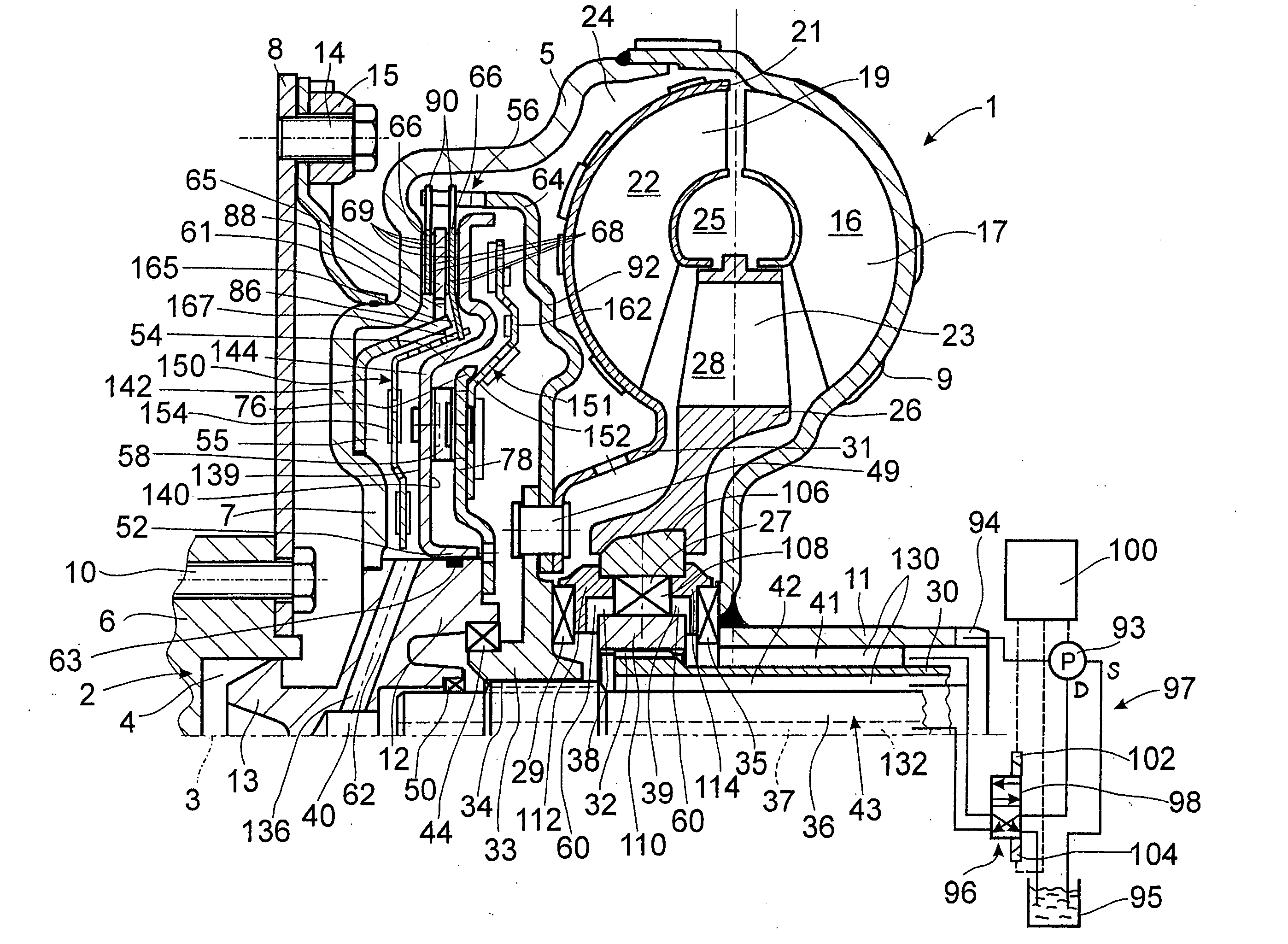
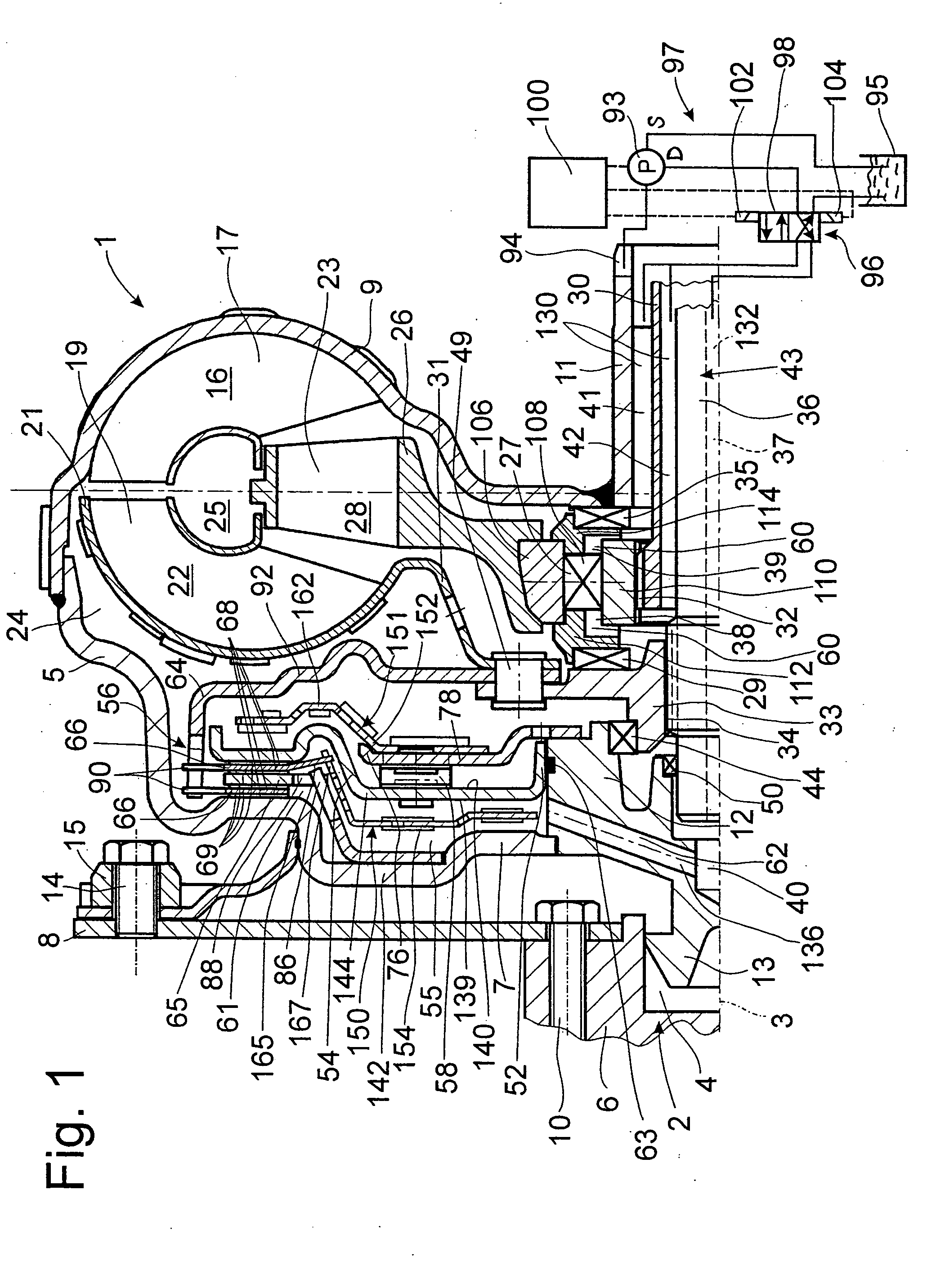
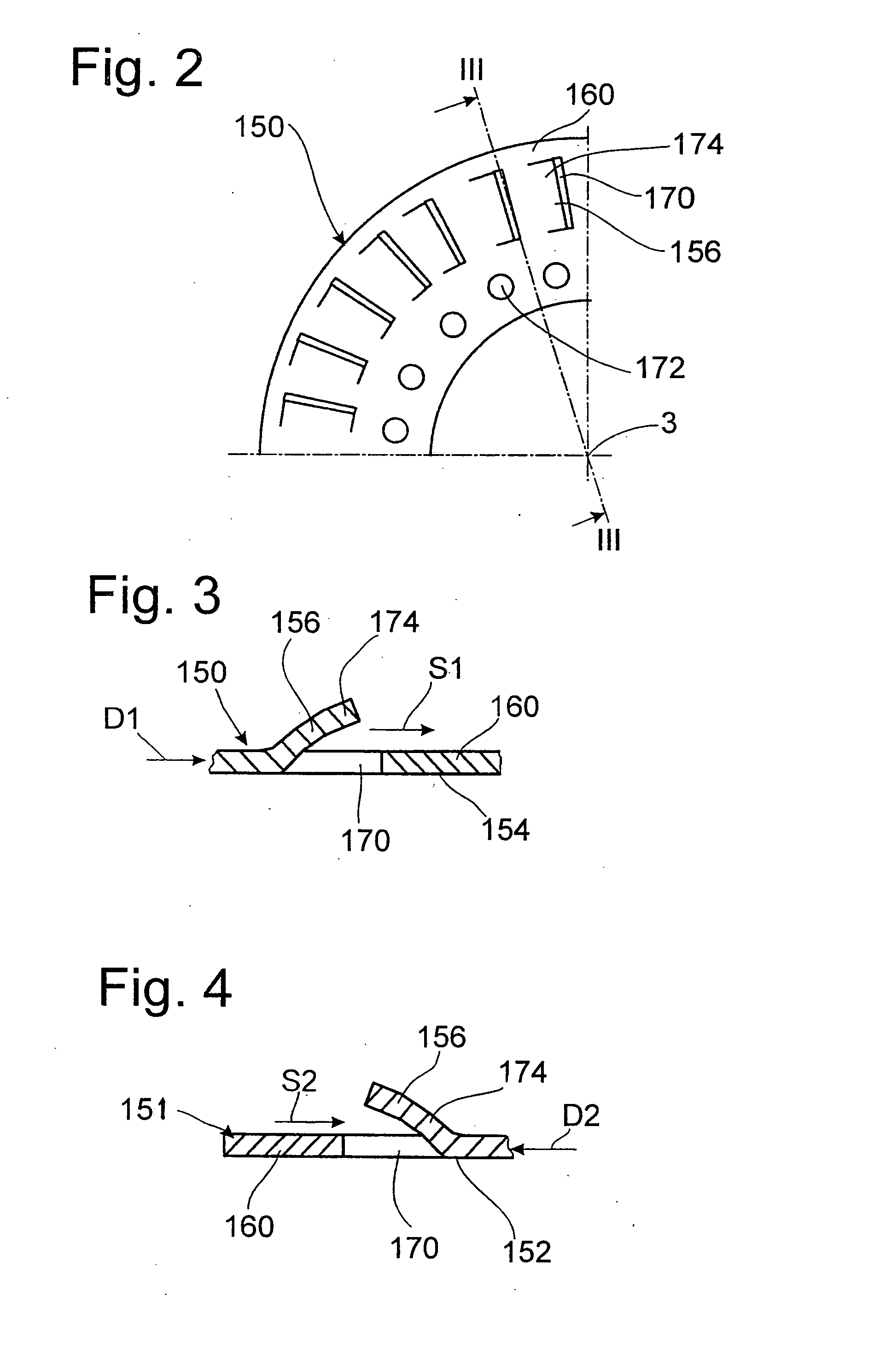
[0012] This task is accomplished by a hydrodynamic clutch device having a flow influencing device located axially adjacent to the piston in at least one of the pressure space and the hydrodynamic circuit. By installing a flow velocity influencing device inside the hydrodynamic circuit, the flow velocity prevailing there is decelerated, whereas, through the installation of the flow velocity influencing device in the pressure space, the effect is achieved there of accelerating the prevailing flow velocity. As a result, the flow velocities in the hydrodynamic circuit and in the pressure space are brought closer together, which has an effect on the pressure conditions in the two spaces, as will be explained below.
[0013] Pressure increase curves which rise in an essentially monotonic manner between the axis of rotation and the area of the radial extension of the bridging clutch develop both in the hydrodynamic circuit and in the pressure space. Because of the higher rotational speed of the turbine wheel on the takeoff side in push mode, the pressure curve in the hydrodynamic circuit rises more quickly than that in the pressure space on the opposite side of the piston. Because of the decrease in the flow velocity in the hydrodynamic circuit and / or the increase in the flow velocity in the pressure space—caused in each case by the flow velocity influencing device—however, an effect is exerted on the pressure increase curves present in the hydrodynamic circuit and / or in the pressure space with the result that the two curves approach each other. As a result, the pressure equalization which tends to occur in the area of the radial extension of the bridging clutch when the bridging clutch is open is hardly perceptible at all in the sense that the positive pressure which would otherwise develop radially inside the bridging clutch because of the flatter pressure increase curve in comparison with that in the hydrodynamic circuit and which would make it more difficult to engage the piston and thus to close the bridging clutch does not, in fact, occur. The buildup of this positive pressure in the pressure space is accordingly avoided almost completely by the flow velocity influencing device.
[0014] Because the flow velocity influencing device causes the pressure-increase curve in the hydrodynamic circuit and the pressure-increase curve in the pressure space to become more similar to each other, the piston requires only a slight positive pressure on the hydrodynamic circuit side to push it toward the pressure space when the clutch engaging process is initiated, especially during operation in push mode, that is, when the rpm's at the takeoff, such as at the turbine wheel, are higher than those at the drive, such as at the clutch housing, especially the drive side housing cover.
