Heat exchanger and manufacturing method of the same

a technology of heat exchanger and manufacturing method, which is applied in the direction of indirect heat exchangers, laminated elements, lighting and heating apparatus, etc., can solve the problems of pressure drop remarkably increased, and fluid not being easily dispersed in the whole flow path, so as to improve the non-uniform rate distribution, improve the heat exchange performance, and eliminate the effect of pressure drop in the fin parallel region

Inactive Publication Date: 2010-02-04
SANYO ELECTRIC CO LTD +1
View PDF11 Cites 7 Cited by
  • Summary
  • Abstract
  • Description
  • Claims
  • Application Information

AI Technical Summary

Benefits of technology

[0013]According to the present invention, the heat exchanger has the flow path of the first fluid and the flow path of the second fluid and performs the heat exchange between both the fluids, and the flow paths include the flat plates each having the inflow port of the fluid on one end thereof and the outflow port of the fluid on the other end thereof and the fins provided in the flat plates. The heat exchanger comprises the fin orthogonal region where the fins cross the flow direction of the fluid from the inflow port to the outflow port; and the fin parallel region where the fins are disposed in parallel with the flow direction of the fluid from the inflow port to the outflow port. Therefore, the fluid can be dispersed in the whole flow paths by the fin orthogonal region, and the fluid can be allowed to flow smoothly in the fin parallel region.
[0014]In consequence, while improving the non-uniform rate distribution by the fin orthogonal region, a disadvantage that the pressure drop increases in the fin parallel region can be eliminated.
[0015]Particularly, as in the second aspect, the fin orthogonal regions are provided on the sides of the inflow port and the outflow port, and the fin parallel region is provided between the respective fin orthogonal regions. In consequence, drift around the inflow port and the outflow port can effectively be eliminated, and the whole flow paths can effectively be utilized, so that the improvement of a heat exchange performance can be realized.
[0016]Furthermore, as in the third aspect, the fins are the offset type fins having the rectangular wavy shape. In consequence, the fins come in face contact with the flat plates, and hence the pressure resistance of the heat exchanger can be improved. Therefore, as in the fourth aspect, as at least one of the first fluid and the second fluid, a high-pressure fluid such as carbon dioxide may be used.
[0017]According to the manufacturing method of the heat exchanger of the fifth aspect, in the heat exchanger according to any one of the first to fourth aspects, when the difference between the maximum flow velocity and the minimum flow velocity of the fluid in the plane crossing the flow direction of the fluid at right angles is integrated with respect to the flow direction of the fluid and the ratio of the fin orthogonal region with respect to the whole is increased, the inflection point where the tilt of the integrated value becomes moderate is obtained as the maximum value, and the ratio of the fin orthogonal region is set within a range of a value larger than zero to a value of the maximum value or less. In consequence, it is possible to manufacture a high-performance heat exchanger capable of improving the non-uniform rate distribution and having less pressure drop.
[0018]Moreover, as in the sixth aspect, when the flat plates and the fins are separately formed and the formed fins are received in the flat plates to manufacture the heat exchanger, it is possible to manufacture the heat exchanger capable of arbitrarily setting the ratio between the fin orthogonal region and the fin parallel region in accordance with an application, use conditions or the like without any noticeable change of a mold.

Problems solved by technology

However, when the fins are arranged so as to cross the flow of the fluid at right angles, an area where the fluid collides with the fins enlarges, and hence the fluid is easily dispersed in the whole flow paths by the fins, and can be allowed to uniformly flow through the whole flow paths, but a problem that a pressure drop remarkably increases has occurred.
On the other hand, when the fins are arranged in parallel with the flow of the fluid, the area where the fluid collides with the fins decreases, and hence the pressure drop decreases, but the fluid is not easily dispersed in the whole flow paths.
Therefore, the fluid cannot uniformly be allowed to flow through the whole flow paths, and the performance of the heat exchanger remarkably lowers.

Method used


Image

  • Heat exchanger and manufacturing method of the same
  • Heat exchanger and manufacturing method of the same
  • Heat exchanger and manufacturing method of the same

Examples


Embodiment Construction

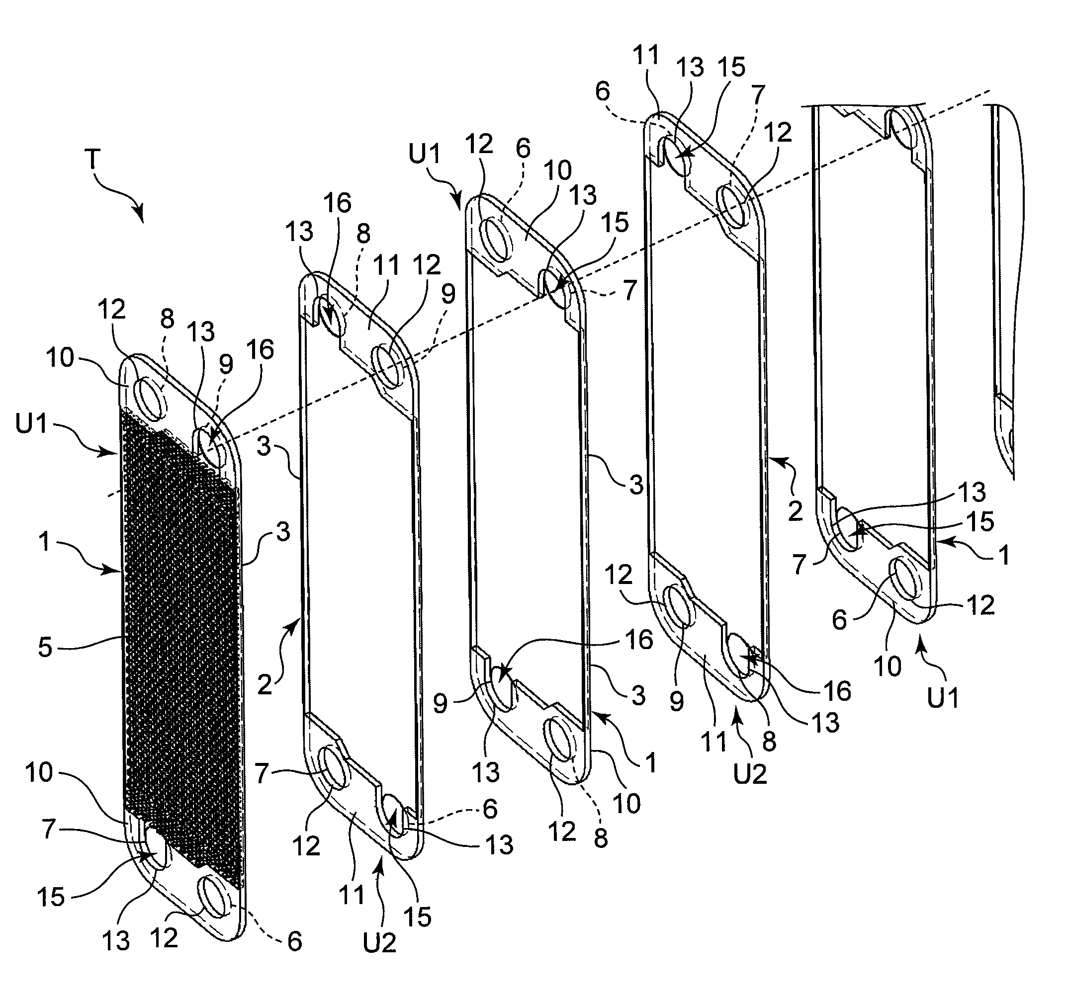
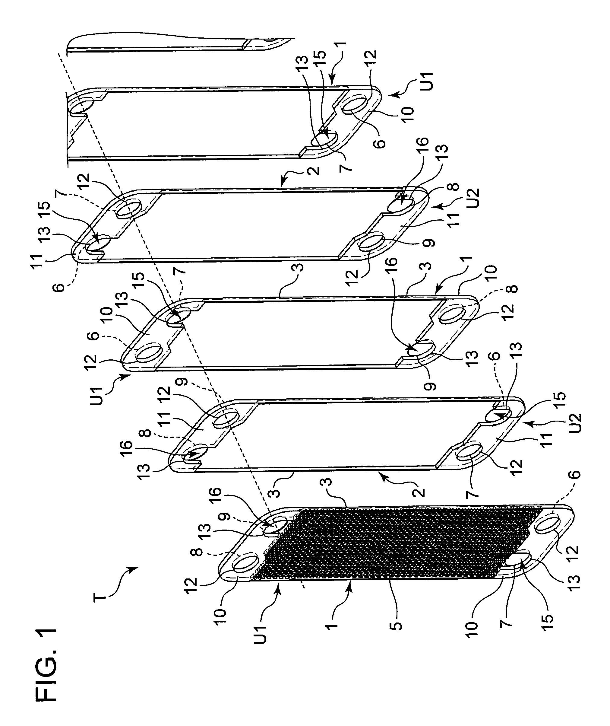
[0045]The present invention relates to a heat exchanger for performing heat exchange between fluids, and has been developed to eliminate a disadvantage that a pressure drop increases in a case where fins are arranged so as to cross fluid flow at right angles and to improve the drift of the fluid in a case where the fins are arranged in parallel with the fluid flow. A purpose of suppressing the pressure drop while improving the non-uniform rate distribution of the fluid is realized by disposing a fin orthogonal region where the fins cross the flow direction of the fluid from an inflow port to an outflow port at right angles and a fin parallel region where the fins are arranged in parallel with the flow direction of the fluid from the inflow port to the outflow port. Hereinafter, embodiments of the present invention will be described in detail with reference to the drawings.

[0046]FIG. 1 is a perspective view schematically showing a constitution of a heat exchanger of one embodiment of...


PUM

PropertyMeasurementUnit
pressureaaaaaaaaaa
pressure dropaaaaaaaaaa
pressureaaaaaaaaaa

Abstract

There is disclosed a heat exchanger capable of suppressing the increase of a pressure drop while improving a non-uniform rate distribution of a fluid. A heat exchanger T of the present invention is constituted of flat plates 1, 2 each having an inflow port 15 of the fluid on one end thereof and an outflow port 16 of the fluid on the other end, and offset type fins 5 provided in the flat plates 1, 2, and includes a fin orthogonal region H where the plate fins 5 cross the flow direction of the fluid from the inflow port 15 to the outflow port 16 at right angles and a fin parallel region V where the plate fins 5 are disposed in parallel with the flow direction of the fluid from the inflow port 15 to the outflow port 16, the fin orthogonal regions H are provided on the sides of the inflow port 15 and the outflow port 16, and the fin parallel region V is provided between the respective fin orthogonal regions H.

Description

BACKGROUND OF THE INVENTION[0001]The present invention relates to a heat exchanger for performing heat exchange between a first fluid and a second fluid, and a manufacturing method of the heat exchanger.[0002]This type of heat exchanger, for example, a heat exchanger including offset type fins is constituted of a plurality of flat plates, and the offset type fins provided between an inflow port formed in one end of each flat plate in a longitudinal direction and an outflow port formed in the other end thereof. The flat plates are provided with flow paths of the fluid which flows into the inflow port of the one end, flows toward the other end through spaces among the fins, and is discharged from the outflow port.[0003]Each of the fins is formed by forming a pair of cutouts at predetermined intervals from shoulders of both side walls of each protrusion having a trapezoidal section to bottom plate portions, and bending the corresponding portions inwardly, and has such an offset shape. ...

Claims


Application Information

Patent Timeline
Patent Type & Authority Applications(United States)
IPC IPC(8): F28F3/00B23P15/26
CPCF25B39/00Y10T29/49378F28F3/027F28D9/005
Inventor TOMOCHIKA, KAZUYOSHISAWADA, NORIOMUKAIYAMA, HIROSHIMATSU, KOTARO
Owner SANYO ELECTRIC CO LTD
Why Eureka
Try Eureka