Co-injection mixing method and apparatus

a technology of liquid chemical components and mixing methods, applied in the direction of mixer accessories, flow mixers, mixers, etc., can solve the problems of not having good manual skills, functional and structural complexity of apparatuses, and not having a number of limits and drawbacks, so as to improve the control of metering and mixing conditions, save a substantial amount of energy, and reduce the effect of pressure drop

Inactive Publication Date: 2008-11-25
AFROS
View PDF25 Cites 8 Cited by
  • Summary
  • Abstract
  • Description
  • Claims
  • Application Information

AI Technical Summary

Benefits of technology

[0011]The main object of this invention is to provide a method for mixing reactive chemical components, in the production of polyurethane foams and moulded articles in polyurethane material, which makes use, in a new and original way, of the turbulency and impingement mixing technology, by means of a self-cleaning mixing apparatus suitably modified to provide an improved and easier control of the metering and mixing conditions, by using a comparatively less pressure drop than in the conventionally mixing apparatuses, thereby saving a substantial amount of energy and achieving a better mixing degree.
[0012]A further object of the invention is to provide a mixing method as defined above, whereby it is possible to use a same pressure drop for injecting the various components into an impingement and turbulence mixing chamber; this makes it possible to mix liquids having very difficult or considerably different miscibility properties from one another, to obtain an intimate mixing and improved mixing degree.
[0013]The mixing method according to this invention can be used with any polyurethane formulation, also containing suspended particles and / or dissolved or nucleated gases; advantageously, it can be used for mixing highly viscous or mutually incompatible liquid components, in that it enables the mixing to be optimised by operating with low feeding pressure values, for example, 40-50% lower than those required by the conventional high-pressure mixing apparatuses.

Problems solved by technology

Even though the conventional high-pressure mixing apparatuses are structurally simple and appreciated for several applications, thanks to their good mixing and self-cleaning characteristics, they nevertheless present a number of limits and drawbacks due to the difficulty in improving their efficiency, in particular in completing an intimate mixing of the chemical components, and in keeping a stoichiometric ratio at the beginning of the injection step.
In the past, attempts were made to obviate such limitation by adopting particular devices for unbalancing the pressures, or by making use of members for throttling the outlet aperture of the mixing chamber, post-mixing chambers and / or devices, all of which tended to functionally and structurally complicate the apparatus.
In fact, the pressure setting operations by means of the injection nozzles are critical also when carried out by an expert operator, require good manual skills, take a long time to be carried out, and normally call for preliminary tests for setting up the entire installation.
Moreover, whenever it is necessary to mix chemical components which are highly viscous, or incompatible with one another from the standpoint of solubility and miscibility, such as for example a lipophilic component and a hydrophilic component, in general very high feed pressures must be used in order to obtain the required mixing; consequently a greater energy consumption is requested and greater structural and functional complications for the entire feeding system for the components to the mixing apparatus.
Lastly, even though the mixing conditions can be improved by reducing, for example, the cross-sectional dimensions of the mixing chamber, because of the need to provide the necessary spacing and seals between the single injection nozzles, and to limit its overall dimensions, in the conventional high-pressure apparatuses it is not possible to fall below certain dimensional limits of the cross-sections of the mixing chambers, and consequently improve the mixing efficacy.
In general, therefore, in apparatuses of the aforementioned kind, it is difficult and complicated to maintain sufficiently satisfactory mixing conditions in terms of proportioning, pressure and optimal mixing of the components, especially upon variation in the flow rates, and during transient phenomena, as to produce a desired and complete reaction process, an adequate state of laminar flow ability of the mixture, and an adequate speed of polymerisation once the components have been mixed and injected into the cavity of a mould or distributed onto a substrate.

Method used


Image

  • Co-injection mixing method and apparatus
  • Co-injection mixing method and apparatus
  • Co-injection mixing method and apparatus

Examples


third embodiment

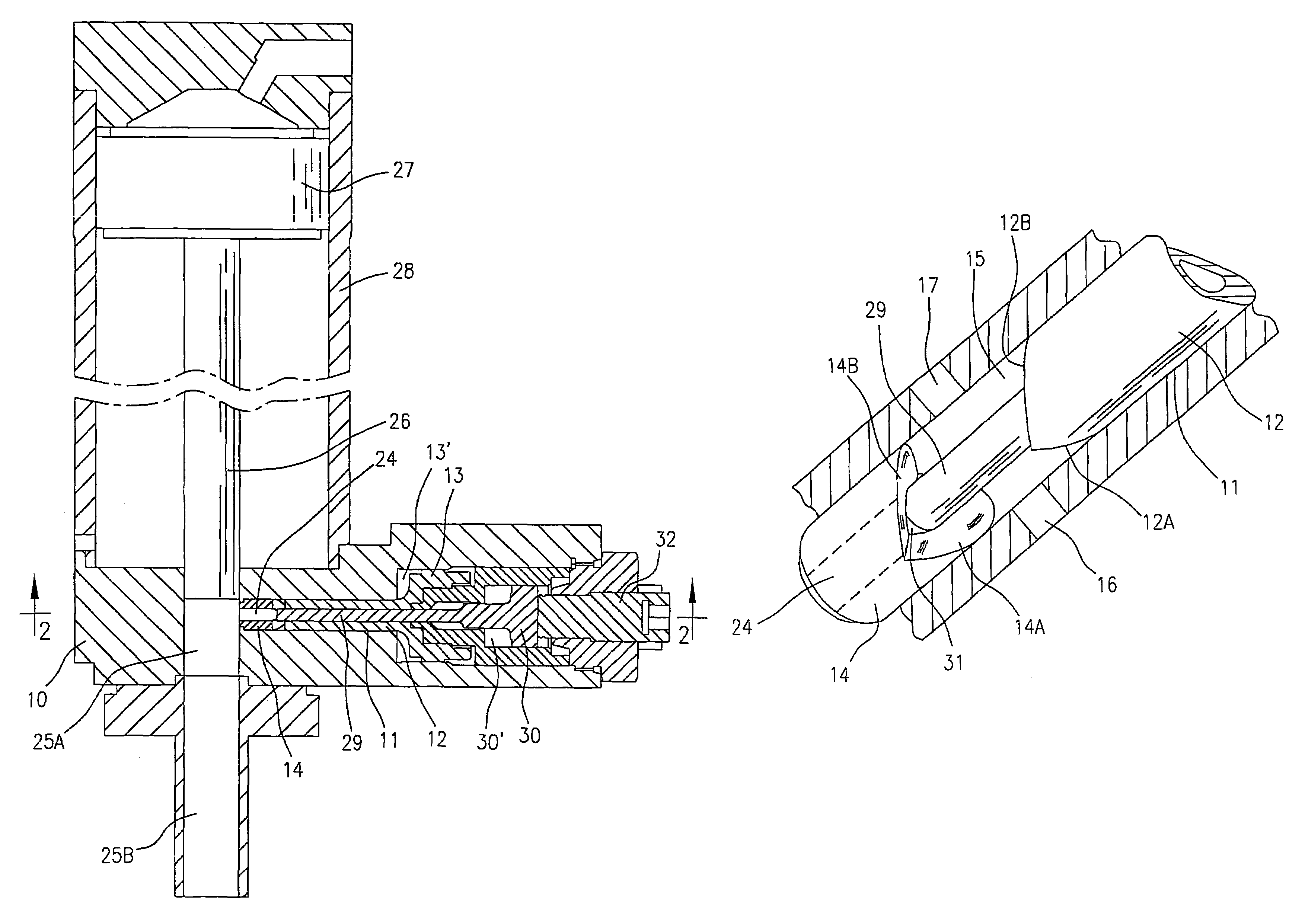
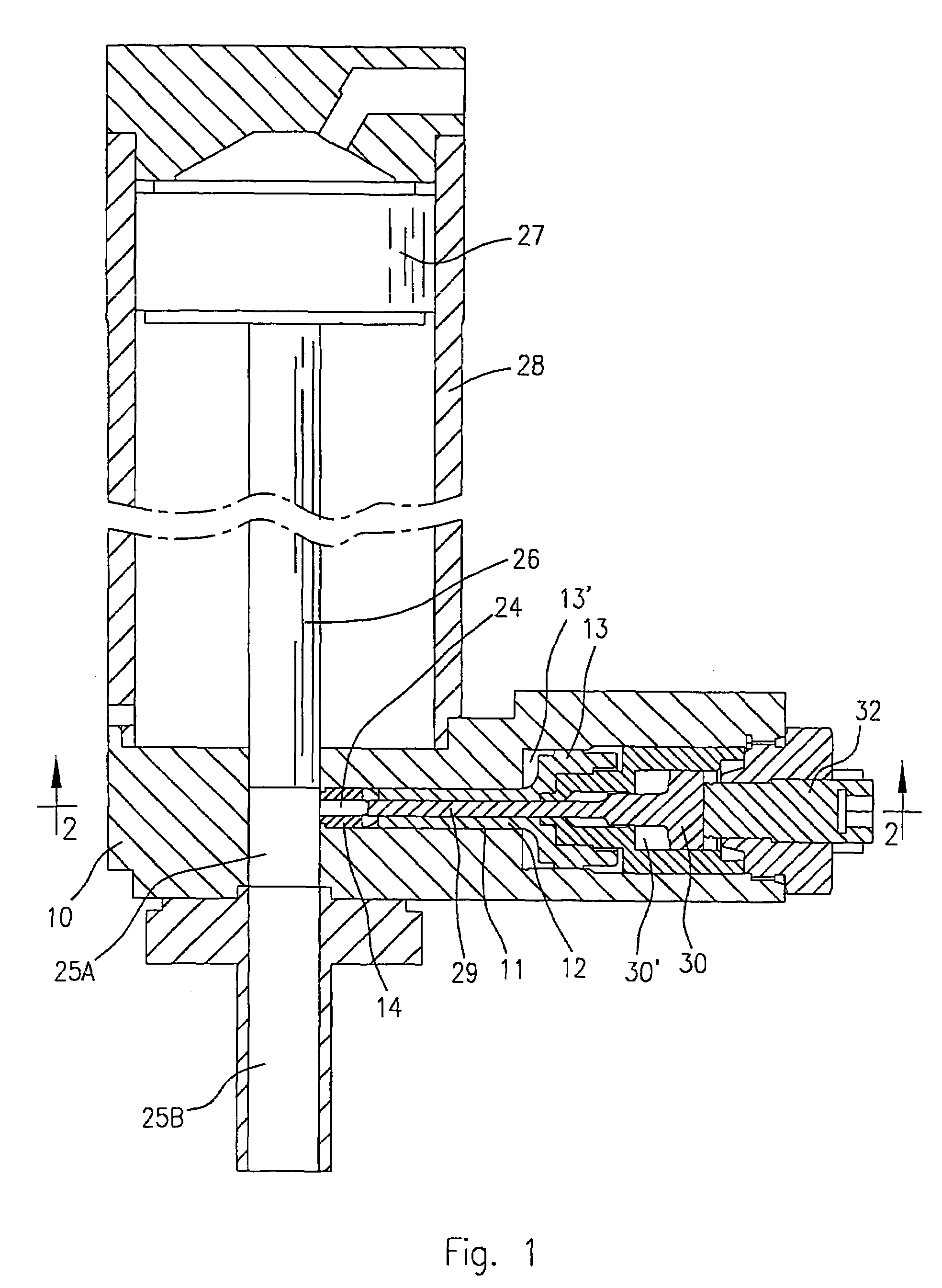
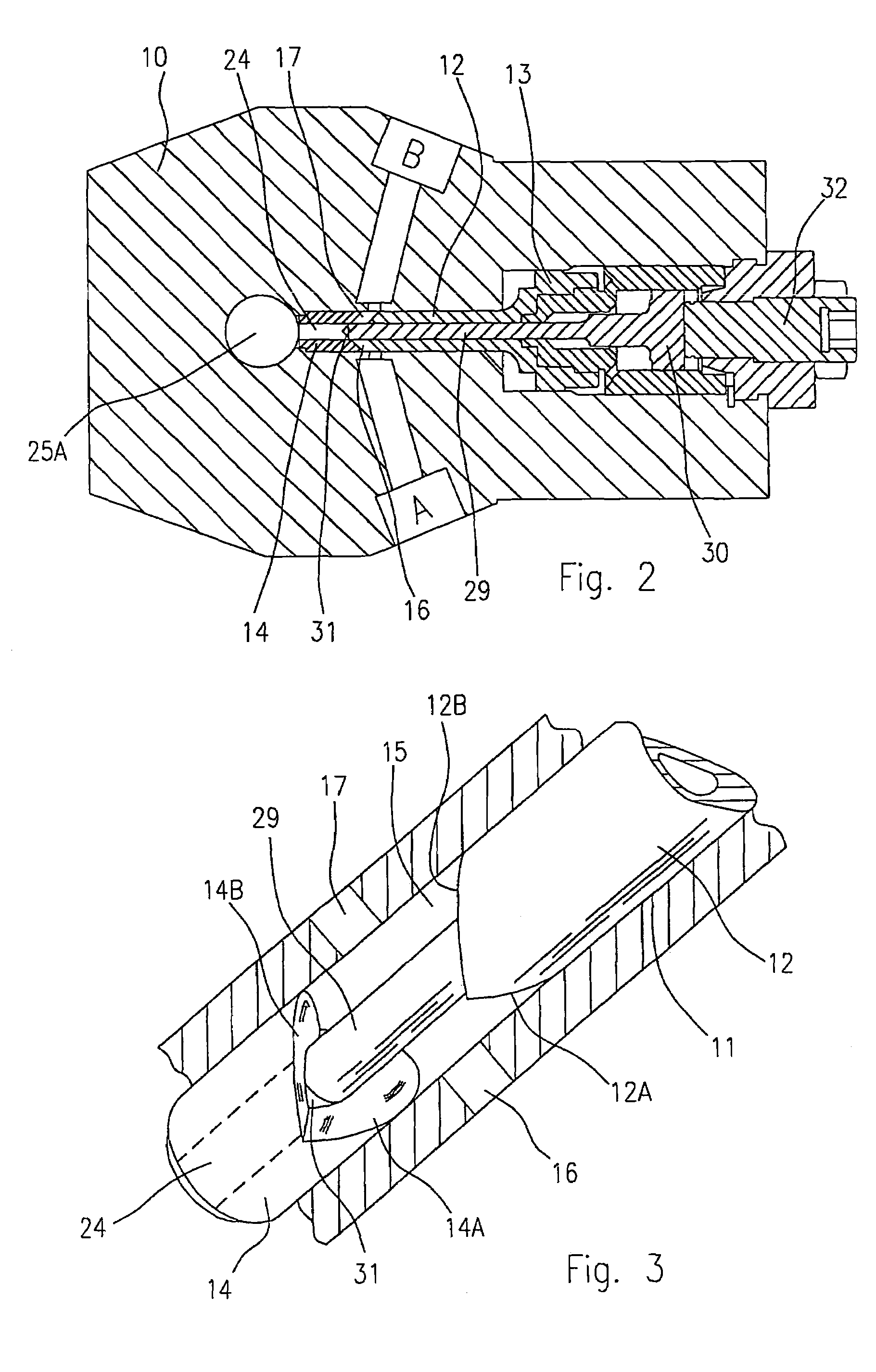
[0098]The FIGS. 13, 14, 15 and 16 show a third embodiment substantially similar to that of the previous figures, which has been modified in the shape of the opposite ends of the spool member 12 and of the fixed bush 14 defining the mixing chamber, to form four jets.

[0099]In this case, the common pressure and feeding chamber 15 can be provided with four inlet ports for four components; consequently, both the tip of the spool member 12 and the rear end of the fixed bush 14 will be provided with crossed V-shaped cuts, or with V-shaped slanting surfaces 12′, 12″ angularly slanting and circumferentially spaced apart from each other, as for example shown at the fore end of the spool member 12 in the perspective view of FIG. 16.

[0100]Here too, the solution of FIGS. 13-16 will operate in a wholly identical way to that described for the previous examples, with the sole difference that now four narrow co-injection orifices, in opposite pairs, are formed, together with the corresponding format...

fourth embodiment

[0102]FIGS. 17, 18 and 19 show a fourth embodiment similar to that of FIGS. 5, 7 and 9 which has been modified to obtain an internal recirculation of the components; in the previous cases, the recirculation of the components could be carried out outside the mixing apparatus, by means of an appropriate valve assembly, in a per se known way.

[0103]Conversely, in the case of FIGS. 17, 18 and 19, the recirculation is carried out inside the apparatus, for example by providing in a per se known manner a recycling port 34 and 35 in correspondence with each inlet port 16 and 17, and by providing the movable spool 12 with longitudinal slots 36 and 37, to flow each component between inlet ports 16, 17 and recirculation ports 34, 35.

[0104]With the exception of the recirculation step, the apparatus of the example shown in FIGS. 17, 18 and 19, again operates in an identical way to that of the previous examples. Therefore, the same reference numbers have again been used to indicate similar or equi...


PUM

PropertyMeasurementUnit
pressureaaaaaaaaaa
pressureaaaaaaaaaa
angleaaaaaaaaaa

Abstract

A method and device (10) for mixing polyurethane-forming liquid chemical components for the production of polyurethane foams, in which positive use is made of the turbulency and swirling action caused by the injection of pressurized jets of chemical components, in order to provide a methodology tending to improve the mixing processes by impingement and by the turbulency induced by a pressure drop in conventional self-cleaning apparatuses.

Description

BACKGROUND OF THE INVENTION[0001]This invention refers to a method and an apparatus for mixing liquid chemical components, in particular for the production of polyurethane foams, in which positive use is made of the turbulency and swirling action caused by the injection of pressurized jets of chemical components, in order to provide a methodology tending to improve the mixing processes by impingement and by the turbulency induced by a pressure drop in conventional self-cleaning apparatuses.PRIOR ART[0002]In the production of polyurethane foams or moulded parts in rigid or flexible polyurethane material, two or more reactive chemical components, with a low boiling agent and / or additives, are mixed in special apparatuses according to known methods; the resulting reactive mixture is injected into a mould or poured on a substrate, where rapidly reacts to form a polyurethane foam slabs or moulded pieces in polyurethane material.[0003]There are basically two mixing technologies, and namel...

Claims


Application Information

Patent Timeline
Patent Type & Authority Patents(United States)
IPC IPC(8): B01F5/04B29B7/76
CPCB29B7/7668B29K2075/00B29B7/7694B29B7/7615
Inventor CORTI, MAURIZIOCORRADI, PIEROFIORENTINI, CARLO
Owner AFROS
Why Eureka
Try Eureka