Climate Control System for Data Center

a data center and climate control technology, applied in the field of data center climate control systems, can solve the problems of air leakage between primary and secondary air streams, rotary heat wheels, and high cost of mechanical climate control systems relying solely on refrigerant or liquid cooling, so as to prevent mixing or cross contamination, prevent the transfer of harmful contaminates, and eliminate leakage

Active Publication Date: 2015-07-23
DYNA TECH SALES CORP
View PDF4 Cites 7 Cited by
  • Summary
  • Abstract
  • Description
  • Claims
  • Application Information

AI Technical Summary

Benefits of technology

[0007]In the present invention, sensible heat rejection of the data center space containing heat generating equipment is achieved by recirculating the conditioned primary air stream through a plate-type cross-flow heat exchanger, in which the cross-flow consists of a totally segregated cooler secondary ambient air stream. The air-to-air cross-flow heat exchanger is comprised of a series of parallel square or rectangular plates, which define a series of orthogonally alternati

Problems solved by technology

Since mechanical climate control systems relying solely on refrigerant or liquid-based cooling are costly and have a negative impact on the environment, there has been an impetus toward the use of heat exchange between cooler ambient air and the heated recirculating air within the data center.
The use of a rotary heat wheel, however, involves several disadvantages Inherent in the design is air leakage between the primary and secondary air streams through the breach in the partition needed to accommodate the rotating heat wheel.
Since brushes and air sealing gaskets cannot completely stop leakage, energy transfer effi

Method used


Image

  • Climate Control System for Data Center
  • Climate Control System for Data Center
  • Climate Control System for Data Center

Examples


Embodiment Construction

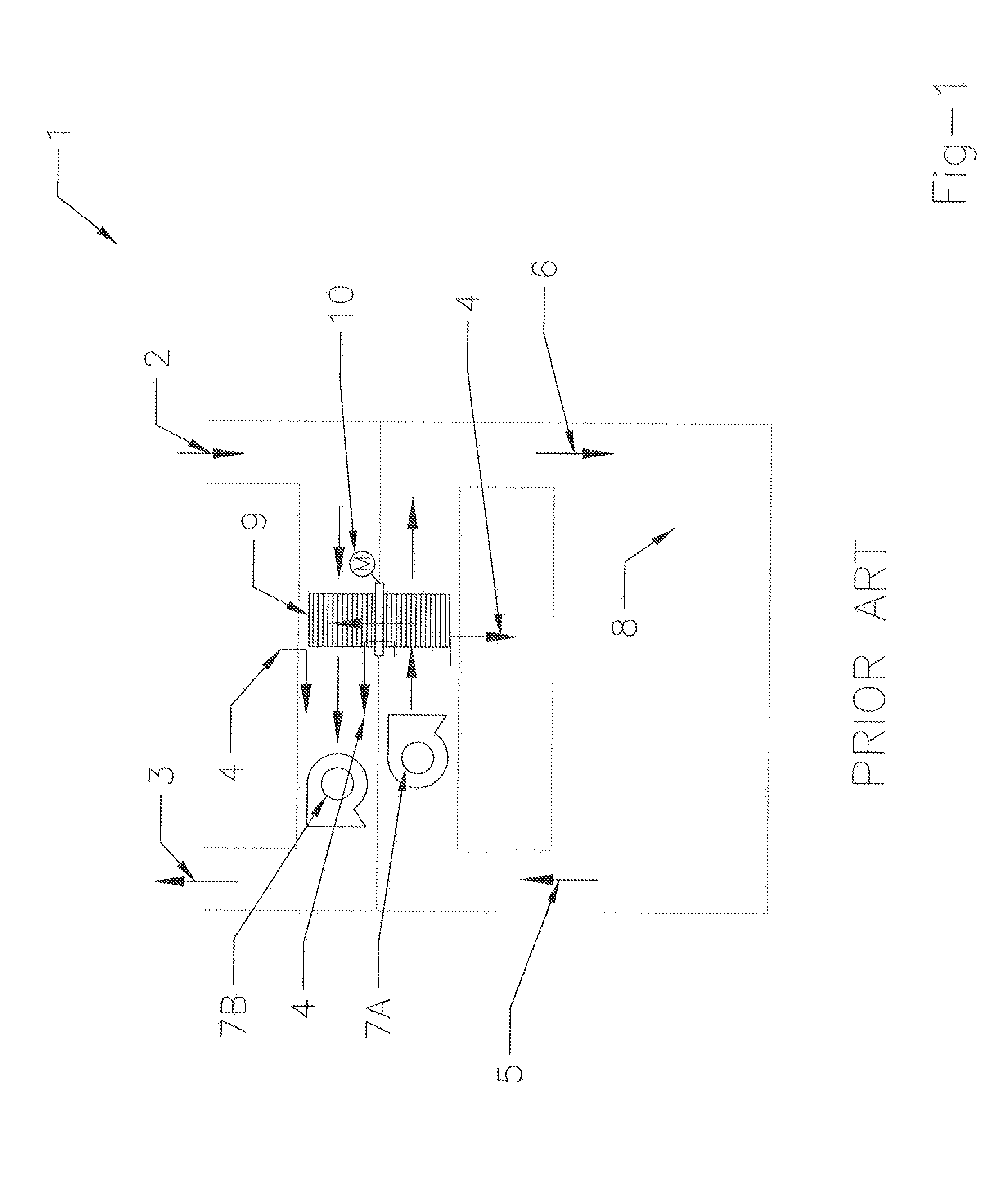
[0027]Referring to FIG. 1, the prior art heat wheel type air-to-air heat exchanger 1 transfers heat generated by a climate-controlled data center space 8 to an outside air stream (OAS) 2 exhausting to ambient 3. The heat wheel 9 rotates, by means of a motor 10, through a partition between a primary air flow, consisting of the recirculating air stream (RAS) 56, and a secondary air flow, consisting of the OAS 23. The RAS consists of a warm return air stream 5 and a conditioned supply air stream 6. The OAS consists of an intake air stream 2 and an exhaust air stream 3. Fans 7A 7B generate pressure to move the primary and secondary air flows through the perforated heat wheel 9. Leakage across the partition 4 between the primary and secondary air flows reduces the heat transfer efficiency of this type of system. The fan position in the system is therefore critical, which limits flexibility of system design for this embodiment.

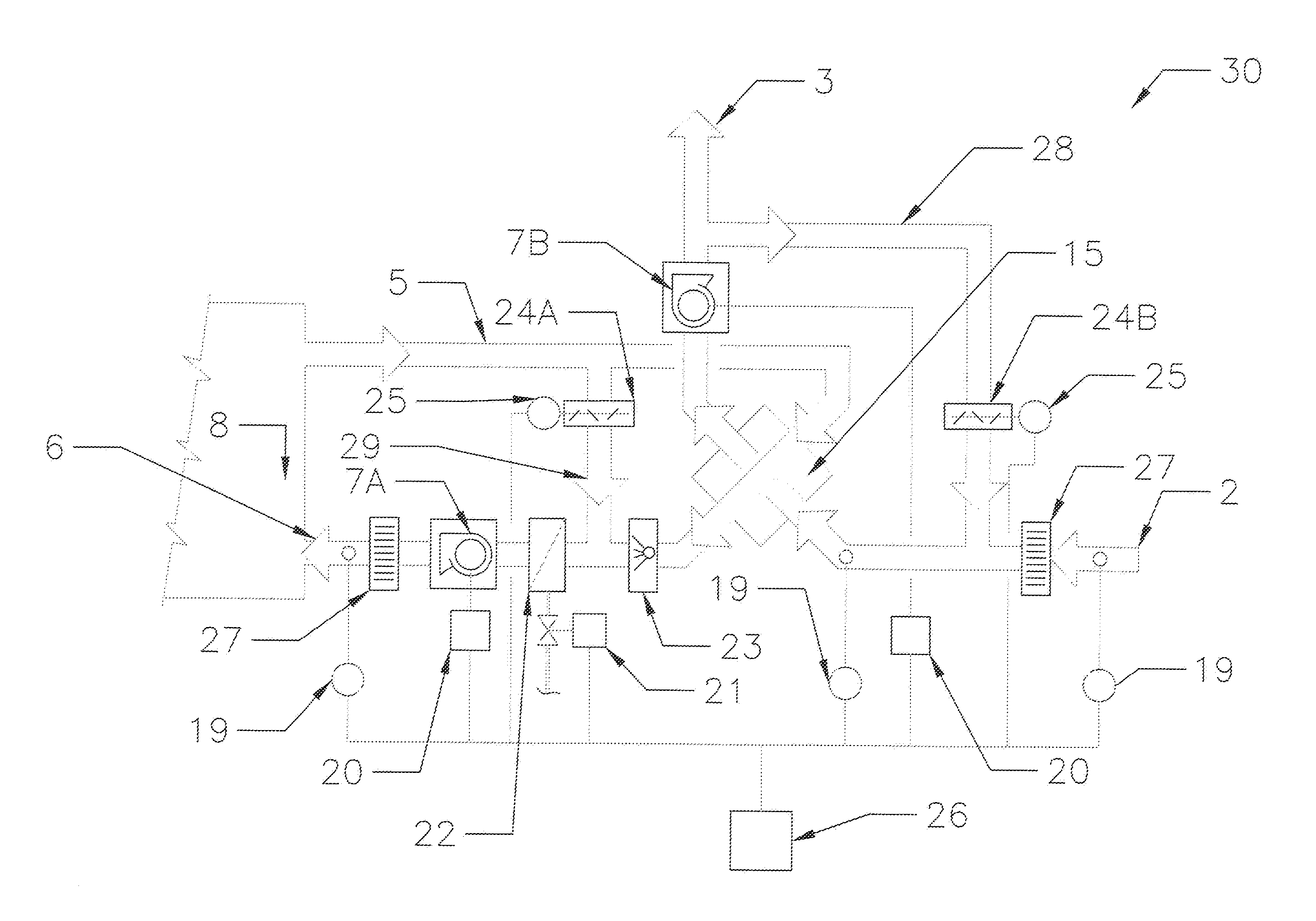
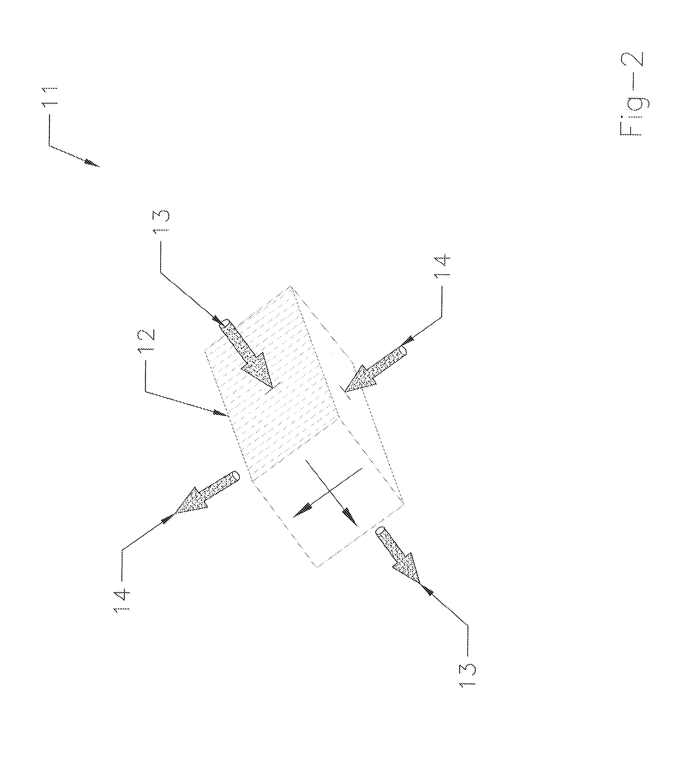
[0028]Referring to FIG. 2, the present invention replaces the ...


PUM


Abstract

Optimized conditioning of Information and Communication Technology (ICT) centers containing sensible heat generating equipment is achieved by indirect air-side economizing. In this process, the conditioned primary air stream is recirculated through a plate-type cross-flow heat exchanger, in which the cross-flow consists of a completely segregated cooler secondary ambient air stream. The air-to-air cross-flow heat exchanger comprises a series of parallel square or rectangular plates, which define a series of orthogonally alternating air passageways. This cross-flow design effectively prevents the mixing or blending of the primary and secondary air streams and thus avoids the efficiency losses and process airstream cross-contamination due to leakage, which is inherent in wheel type heat exchangers. The unique modular tunnel design of the cross-flow plate heat exchanger arrangement offers unit scalability and adjustability for various capacities and space demands. Real-time sensing of thermal demands and variable capacity control, coupled with on-demand mechanical cooling and humidification provisions, facilitate continuous operational optimization in all demands and ambient conditions.

Description

REFERENCE TO RELATED APPLICATION[0001]The present application claims the benefit of the filing date of Provisional Application No. 61 / 929,024, filed Aug. 18, 2014.FIELD OF INVENTION [0002]The present invention relates to the technical field of devices and methods for controlling temperature and humidity in data centers. More particularly, the present invention relates to a system of temperature and humidity conditioning of a primary recirculation air stream by means of heat transfer with a cooler secondary air stream via indirect air side economizing.BACKGROUND OF THE INVENTION[0003]Data centers contain information and communications technology (ICT) equipment, such as server and network equipment as well as computers. Depending on the design of such equipment, it generates a comparatively large quantity of sensible heat that must be continually removed so as to maintain the data center climate within a design range of temperature and humidity.[0004]Since mechanical climate control ...

Claims


Application Information

Patent Timeline
IPC IPC(8): H05K7/20
CPCH05K7/20836H05K7/20745H05K7/206H05K7/207H05K7/20754
Inventor MORNAN, BRIAN J.BEITZ, FRANK J.ALMERINI, NICHOLAS J.
Owner DYNA TECH SALES CORP
Why Eureka
Try Eureka