Vehicle center pillar structure

a technology for center pillars and vehicles, applied in vehicle arrangements, roofs, transportation and packaging, etc., can solve problems such as impact loads on center pillars

Active Publication Date: 2006-09-21
GM GLOBAL TECH OPERATIONS LLC
View PDF13 Cites 63 Cited by
  • Summary
  • Abstract
  • Description
  • Claims
  • Application Information

AI Technical Summary

Problems solved by technology

Furthermore, the center pillar may be subjected to impact loads exerted on the doors in a vehicle side-impact scenario.

Method used


Image

  • Vehicle center pillar structure
  • Vehicle center pillar structure
  • Vehicle center pillar structure

Examples


Embodiment Construction

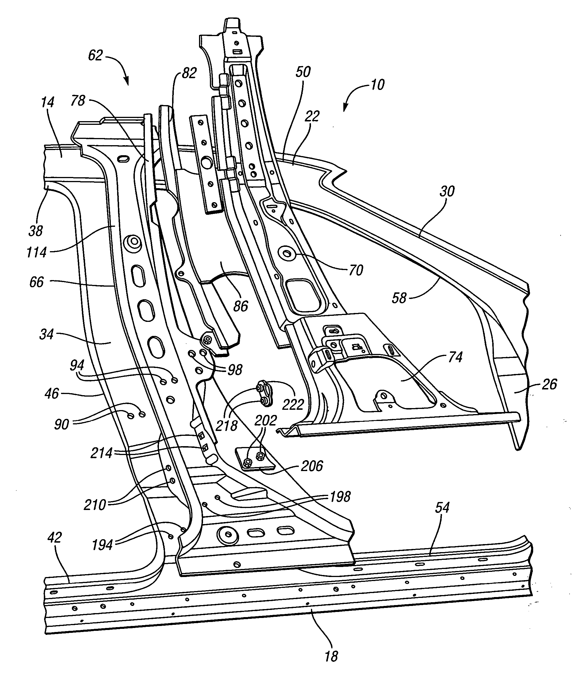
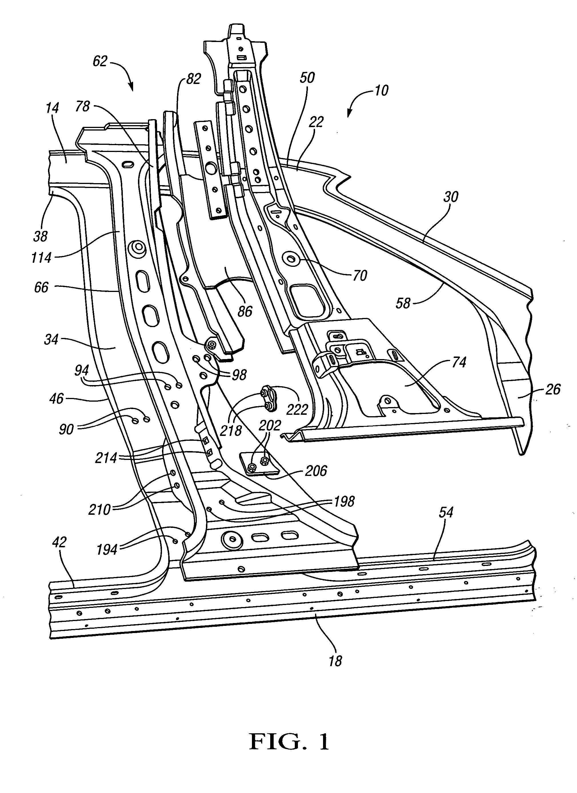
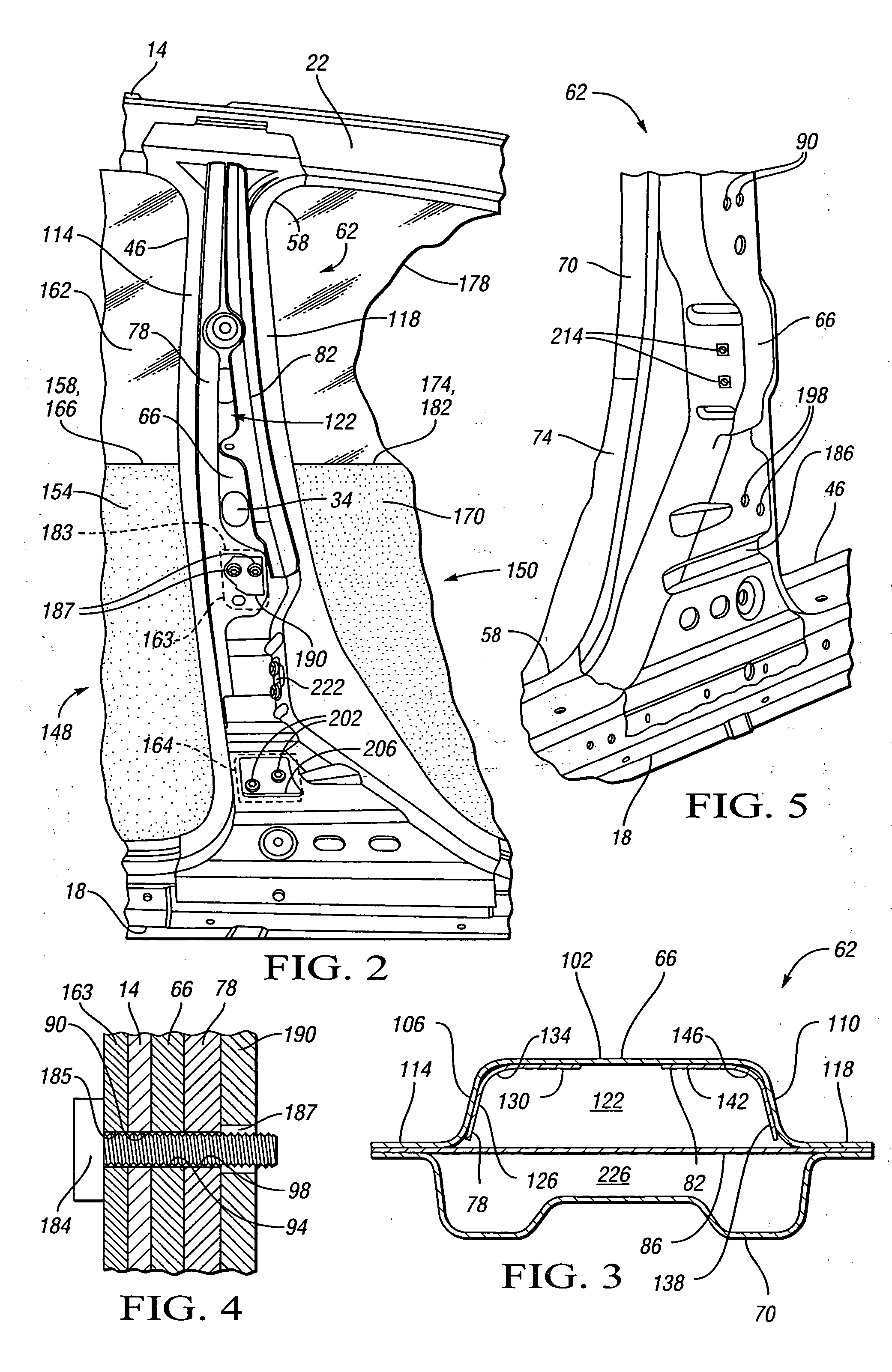
[0017] The first channel reinforcement 78 is characterized by two segments 126, 130 separated by a curved segment 134. Segment 126 is rigidly connected to sidewall 106 such as by welding. Segment 130 is rigidly connected to the outer wall 102 such as by welding. Thus, the first channel reinforcement 78 sufficiently interconnects the outer wall 102 and the sidewall 106 to transfer loads therebetween irrespective of load vector. Similarly, the second channel reinforcement 82 has two segments 138, 142 separated by a curved segment 146. Segment 138 is rigidly connected to sidewall 110 such as by welding. Segment 142 is rigidly connected to outer wall 102 such as by welding. Thus, the second channel reinforcement 82 sufficiently interconnects the outer wall 102 and the sidewall 110 to transfer loads therebetween irrespective of load vector.

[0018] The channel reinforcements 78, 82 are preferably formed of ultra high strength steel, and thus have a significantly higher strength than the o...


PUM


Abstract

A vehicle body includes a center pillar structure including an outer reinforcement having an outer wall and two side walls defining a channel. Two reinforcements are located within the channel, each rigidly interconnecting the outer wall with a respective one of the sidewalls. A tension panel preferably interconnects the two sidewalls. The center pillar structure is characterized by continuity of strength along its height and increased resistance to vertical compressive loads.

Description

TECHNICAL FIELD [0001] This invention relates to vehicle center pillar structures. BACKGROUND OF THE INVENTION [0002] Passenger vehicles often include a center pillar, also sometimes referred to as a “B pillar,” between front and rear door openings. The center pillar typically extends from a floor pan and rocker panel upward to a vehicle roof. The center pillar typically supports a striker that engages a latch on a front door to releasably maintain the front door in a closed position. The center pillar also typically supports hinges that are pivotably connected to a rear door. Thus, the center pillar provides support for front and rear side doors as well as for the vehicle roof. Furthermore, the center pillar may be subjected to impact loads exerted on the doors in a vehicle side-impact scenario. [0003] The cross-sectional geometry of a typical center pillar is smaller above the beltline of the doors than below, in part to minimize obstruction of the view through the door windows. F...

Claims


Application Information

Patent Timeline
Patent Type & Authority Applications(United States)
IPC IPC(8): B62D25/02
CPCB62D25/04
Inventor DINGMAN, MARK T.SWARTZELL, TERRY A.WANG, JAMES JENYINGSHARMA, AMIT
Owner GM GLOBAL TECH OPERATIONS LLC
Why Eureka
Try Eureka