Tension-based non-pneumatic tire

a non-pneumatic tire and tire technology, applied in the field of non-pneumatic tires, can solve the problems of reducing affecting the service so as to prolong the life of the tire, reduce the risk of flatness, and improve the service life.

Active Publication Date: 2009-11-19
BRIDGESTONE AMERICAS TIRE OPERATIONS LLC
View PDF99 Cites 79 Cited by
  • Summary
  • Abstract
  • Description
  • Claims
  • Application Information

AI Technical Summary

Benefits of technology

[0011]A major advantage of using a non-pneumatic tire compared to a standard tire is eliminating flat tires. If a portion of the web is compromised, the load will be redistributed through other elements of the web by virtue of the fact that the web is interconnected, prolonging the life of the tire. In. addition, by not carrying any significant load along a footprint region where the tire contacts a surface, a smoother ride results since the non-pneumatic tire is less susceptible to shock and vibration.

Problems solved by technology

However, along with their advantages, pneumatic tires still possess some drawbacks.
The material that encloses standard pneumatic tires is susceptible to leaking the pressurized air it tries to withhold.
As a result, loss of pressure causes the tire to flatten in the area where the load is applied, subjecting a larger portion of the tire to the load with every revolution, leading to quicker degradation of the tire.
Furthermore, a tire reliant upon pressurized air is susceptible to being punctured leading to rapid release of the pressurized air.

Method used


Image

  • Tension-based non-pneumatic tire
  • Tension-based non-pneumatic tire
  • Tension-based non-pneumatic tire

Examples


example

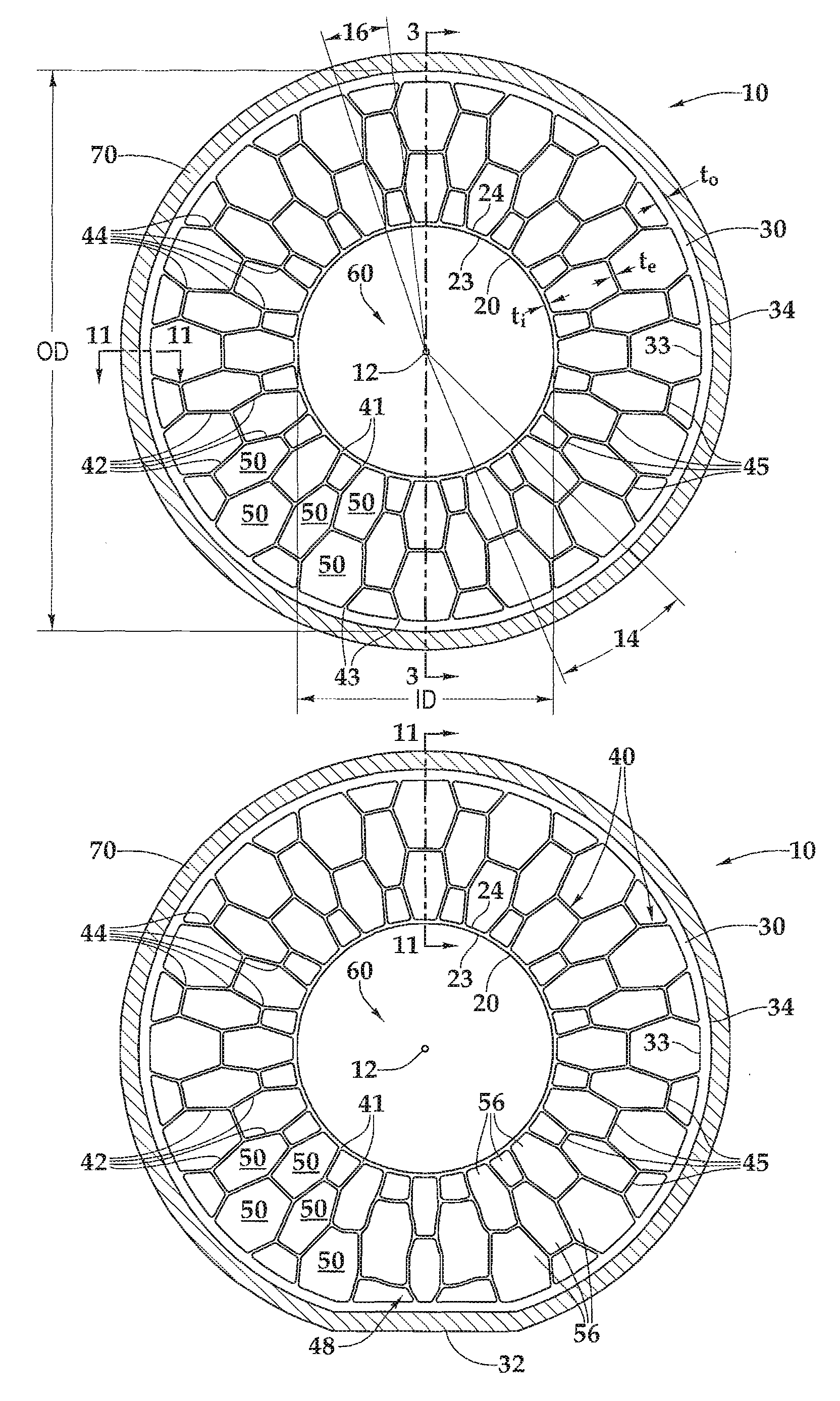
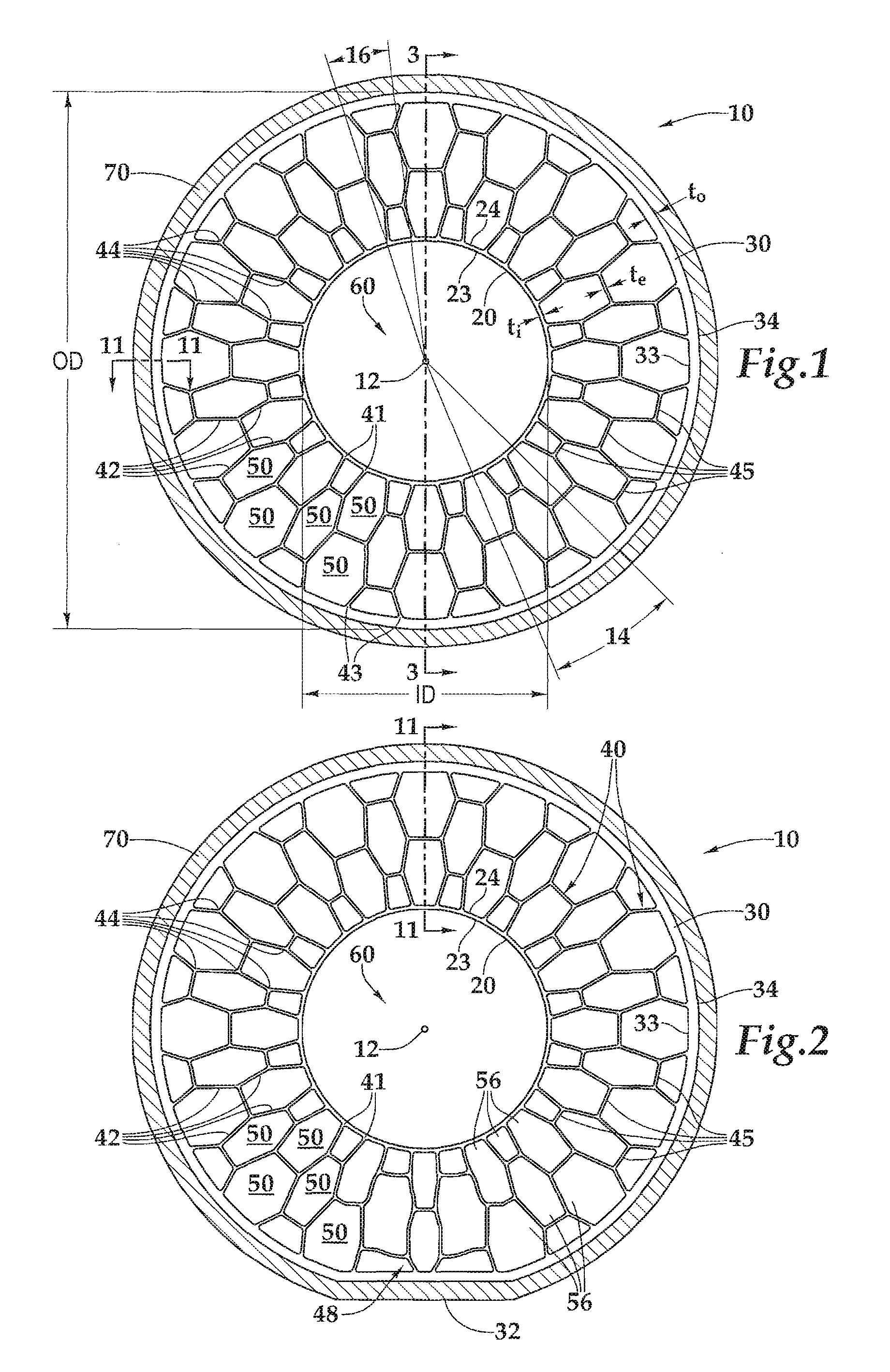
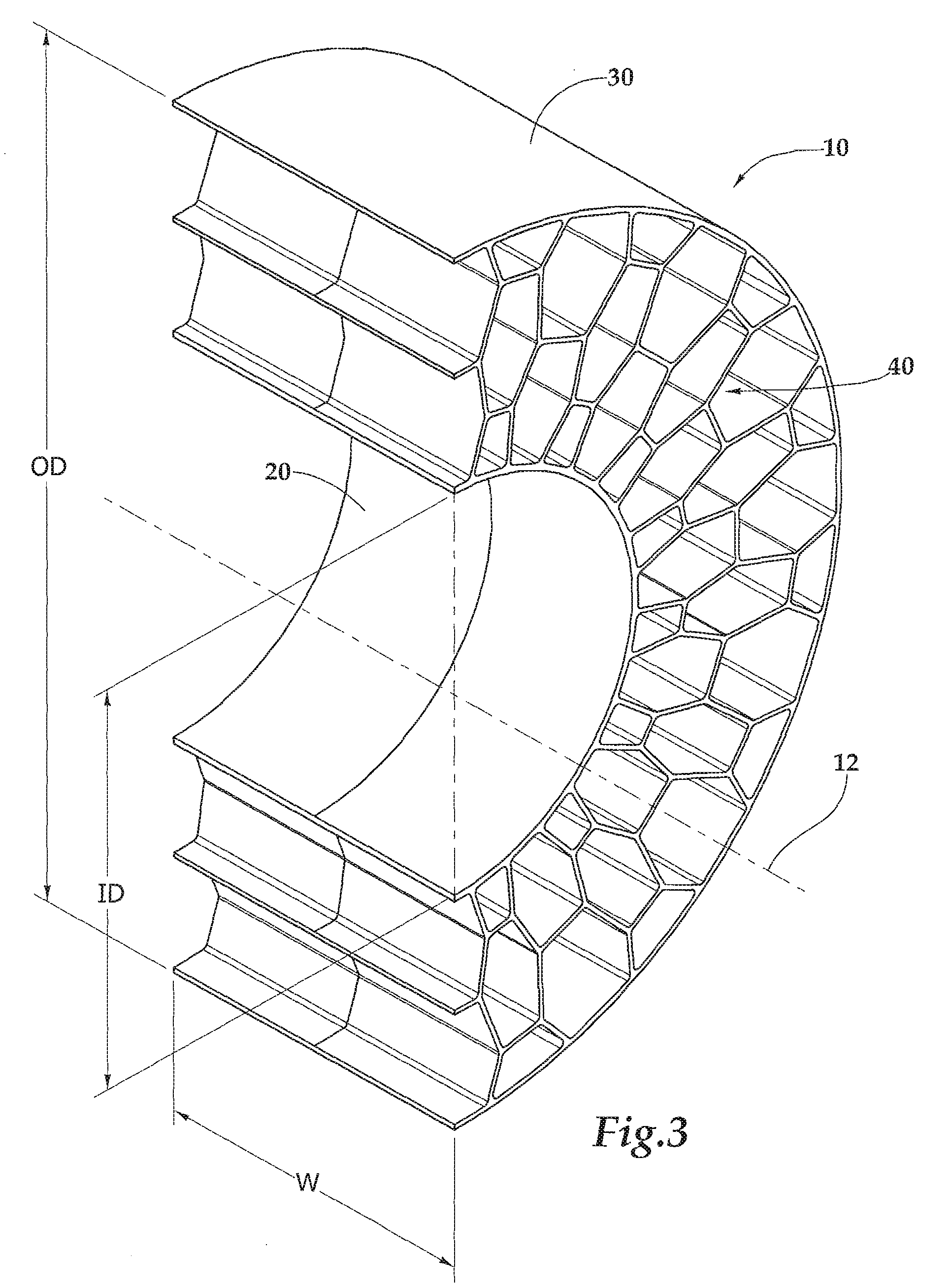
[0075]In one embodiment, a non-pneumatic tire 10 possesses the interconnected web 40 of the configuration shown in FIGS. 1 & 2. Tire 10 has a radius of about 9.5 inches and hub 60 has a radius of about 4⅜ inches.

[0076]In general, the force required for buckling of a column is governed by the equation: F_buckling=(KEIπ̂2) / l̂2 where K=a constant whose value depends on how the ends of the column are affixed, E=tensile modulus, I=the area moment of inertia, and l=the unsupported length of the column.

[0077]If each web element 42 of interconnected web 40 is modeled as its own thin column, the radially innermost elements will be fixed at one end and free to move laterally at another end. In this instance, K=¼.

[0078]In this example, interconnected web 40 and generally annular outer ring 30 are made of a similar material having a tensile modulus, E, of about 21 MPa or 3050 psi.

[0079]Tire 10 may be about 8 inches wide and each web element 42 of interconnected web 40 may be between about 0.04 ...


PUM


Abstract

A non-pneumatic tire for supporting a load by working in tension comprising a generally annular inner surface, a generally annular outer ring, and an interconnected web having a plurality of web elements and comprising a plurality of generally polygonal openings. Web elements are sized, oriented and comprised of a material that facilitates buckling when subjected to a compressive load. By buckling, those elements in a deformed portion of the tire between a hub and a footprint region where the tire contacts a surface may assume a significantly reduced portion of the load, if any. This causes web elements in other portions of the interconnected web to operate in tension to support the load. Since the tire is non-pneumatic, it may be easier to maintain and may have a longer life than standard pneumatic tires since it eliminates the possibility of blowouts, flat tires, or tires operating with low air pressure. By virtue of the portion of the tire in the footprint region not bearing a significant portion of the load, non-pneumatic tire may also exhibit a more comfortable ride subject to less noise and vibration and improved handling capabilities.

Description

[0001]This invention was made, in part, with United States government support awarded by the United States Army Research Laboratory under grant number W911NF-06-2-0021. Accordingly, the United States may have certain rights in this invention.BACKGROUND OF THE INVENTION[0002]1. Field of the Invention[0003]The present invention is directed to a non-pneumatic tire (NPT) or combination of a tire and hub that supports an applied load by working in tension and is capable of serving as a replacement for pneumatic tires and an improvement over other forms of non-pneumatic tires.[0004]2. Description of the Related Art[0005]Non-pneumatic, or airless, tires have historically been comprised largely of an entirely solid substance. These solid tires made the ride rather uncomfortable for passengers and caused greater damage to the suspension of a vehicle, which had to compensate for their lack of “give.” Eventually, it was found that putting pressurized air in tires created a more comfortable rid...

Claims


Application Information

Patent Timeline
Patent Type & Authority Applications(United States)
IPC IPC(8): B60B9/00
CPCB60B9/00B60B9/04Y10T152/10387B60C7/22Y10T152/10297B60C7/12
Inventor MANESH, ALITERCHA, MIKEAYODEJI, OLUKEMIANDERSON, BRIANMELISKA, BRIAN J.CERANSKI, FIDELIS
Owner BRIDGESTONE AMERICAS TIRE OPERATIONS LLC
Why Eureka
Try Eureka