No/low skid device

Active Publication Date: 2022-03-01
DAVIS JAMES ROBERT
View PDF32 Cites 0 Cited by
  • Summary
  • Abstract
  • Description
  • Claims
  • Application Information

AI Technical Summary

Benefits of technology

[0004]The specific problem of extreme tire wear during landing is addressed and can be rectified by instituting tire rotation at or near the ground speed of the aircraft involved. The resul

Problems solved by technology

During this time, large billows of blue smoke from t

Method used


Image

  • No/low skid device
  • No/low skid device

Examples


Embodiment Construction

[0010]The following detailed description is provided to assist the reader in gaining a comprehensive understanding of the methods, products, and / or systems, described herein. However, various changes, modifications, and equivalents of the methods, products, and / or systems described herein will be apparent to an ordinary skilled artisan.

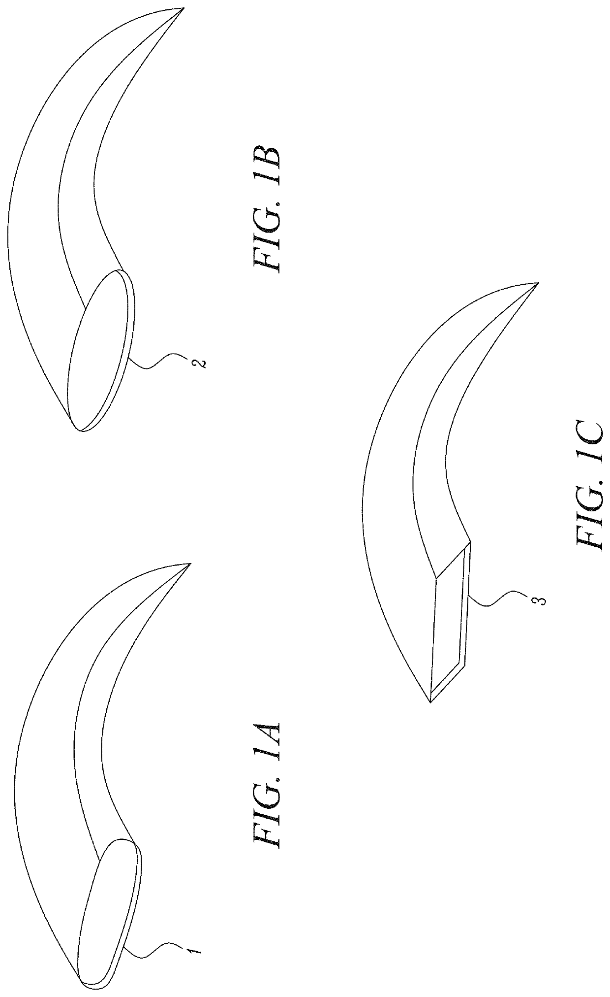
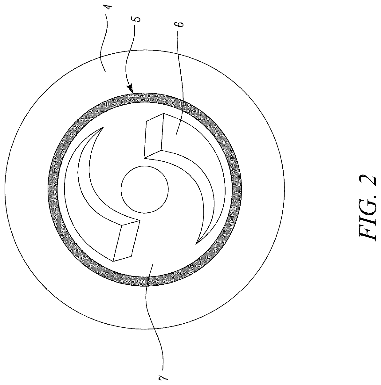
[0011]The invention addresses this with the use of a hub-cap using various air capturing shapes. These protrude from the wheel assembly and can include scoops, cups or slats, depending on RPM required and speed of aircraft when landing.

[0012]When the aircraft is about to land, wind speeds can reach 120-175 mph under the fuselage. At this point, the energy is captured by the captive design of the hub-cap and rotation of the wheel assembly starts in the direction desired. This use of energy in this fashion can be viewed when looking at a wind powered generator or an old fashioned wind-mill.

[0013]The hub-cap includes it being a circular shape and diamete...


PUM


Abstract

An aircraft hubcap/wheel cover which uses ambient airflow (120 mph-175 mph) to rotate wheels on the landing gear of an aircraft accomplished by using slightly protruding slats, blades, scoops or other air capturing shapes, (once the landing gear has been lowered). These air capturing shapes are integrated as part of the hubcap/wheel cover during manufacture and are directly determined by ground speed applicable to that aircraft with the ultimate purpose being tire longevity. The wheel cover hubcap is a single piece design and has no moving parts.

Description

CROSS REFERENCE TO RELATED APPLICATIONS[0001]This application claims priority under 35 USC § 119(e) to U.S. Provisional Application No. 62 / 597,291 filed Dec. 11, 2017 the entire contents of which is herein incorporated by reference in its entirety.BACKGROUND OF THE DISCLOSUREField of the Invention[0002]This invention relates specifically to larger commercial aircraft and the tire wear thereof. The reduction of pre-mature tire wear is the nucleus of this invention.Description of the Related Art[0003]Wheels of most aircraft are subjected instantaneous contact with the tarmac (runway) when landing. During this time, large billows of blue smoke from the skidding of tires is easily evident and prolific.SUMMARY OF THE INVENTION[0004]The specific problem of extreme tire wear during landing is addressed and can be rectified by instituting tire rotation at or near the ground speed of the aircraft involved. The result of this would be no / low skid, and / or an increase in tire longevity, and a g...

Claims


Application Information

Patent Timeline
IPC IPC(8): B64C25/40B64C25/36B60B7/00
CPCB64C25/40B64C25/36B60B7/0013B60Y2200/51B60B7/0066B60B19/00B60B2900/1212B60B2900/321B60Y2200/50Y02T10/86
Inventor DAVIS, JAMES ROBERT
Owner DAVIS JAMES ROBERT
Why Eureka
Try Eureka