Pneumatic tire

a technology of pneumatic tires and quarter-point sections, which is applied in the direction of heavy-duty vehicles, vehicle components, non-skid devices, etc., can solve the problems of uneven wear in the quarter-point section, the largest amount of wear, and slippage between the tread surface and the road surface, so as to prolong the life of the tire and improve the wear resistance of the quarter-point section

Inactive Publication Date: 2014-06-10
BRIDGESTONE CORP
View PDF24 Cites 0 Cited by
  • Summary
  • Abstract
  • Description
  • Claims
  • Application Information

AI Technical Summary

Benefits of technology

[0016]The present invention can provide a pneumatic tire capable of providing a greatly extended tire lifetime through great improvement of the wear resistance of the quarter point sections of the tread contact width.

Problems solved by technology

The uneven wear in the quarter point sections, where the amount of wear is the largest, is mainly due to slippage occurring between a tread surface and a road surface in a direction perpendicular to the tire equator line and outward of the tire.
Moreover, for a pattern having a circumferential-direction main groove, there is strong tendency that the slippage between the tread surface and the road surface occurs in a direction perpendicular to a wall portion of the circumferential-direction main groove.

Method used


Image

  • Pneumatic tire
  • Pneumatic tire
  • Pneumatic tire

Examples


modification 1

[0034]In the description of the pneumatic tire 1 according to the above-described embodiment, only the two circumferential-direction main grooves 13 and the multiple lug grooves 15 are formed in the tread portion 7 (the so-called tread surface). However, the following modification may be made for the embodiment. Note that elements and portions which are the same as or similar to those in the pneumatic tire 1 according to the above-described embodiment are denoted by the same or similar reference signs, and different elements and portions are mainly described.

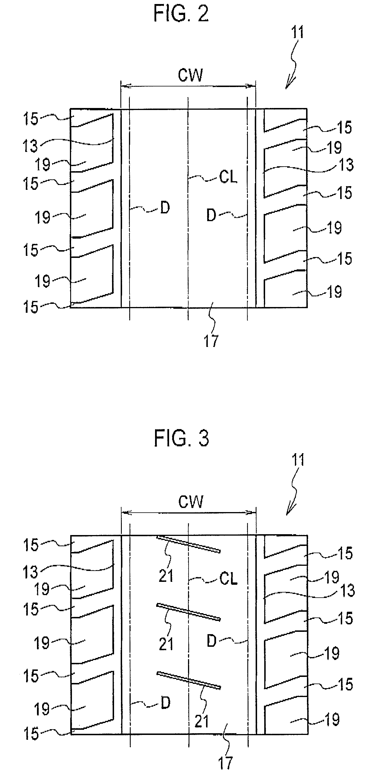
[0035]FIG. 3 is a development view of a tread pattern of a pneumatic tire according to Modification 1. As shown in FIG. 3, multiple width-direction narrow grooves 21 are formed in center land portion 17 defined by the circumferential-direction main grooves 13. Each of the width-direction narrow grooves 21 extends in the tread width direction, and has a width of 0.5 to 5.0% of the tread contact width TW.

[0036]Each of the width-di...

modification 2

[0038]In the description of the pneumatic tire 1 according to the above-described embodiment, only the two circumferential-direction main grooves 13 and the multiple lug grooves 15 are formed in the tread portion 7. However, the following modification may be made for the embodiment. Note that elements and portions which are the same as or similar to those in the pneumatic tire 1 according to the above-described embodiment are denoted by the same or similar reference signs, and different elements and portions are mainly described.

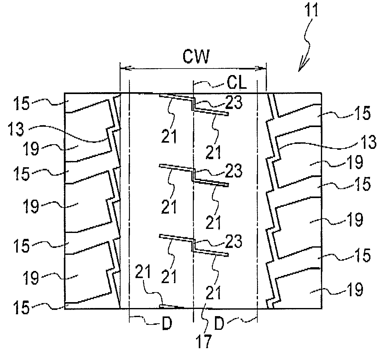
[0039]FIG. 4 is a development view showing a tread pattern of a pneumatic tire according to Modification 2. As shown in FIG. 4, width-direction narrow grooves 21 and a circumferential-direction narrow groove 23 are formed in the center land portion 17 defined by the circumferential-direction main grooves 13. Each of the width-direction narrow grooves 21 extends in the tread width direction, and has a width of 0.5 to 5.0% of the tread contact width TW. The ci...

modification 3

[0042]In the description of the pneumatic tire 1 according to the above-described embodiment, only the two circumferential-direction main grooves 13 extending linearly in the tire circumferential direction and the multiple lug grooves 15 are formed in the tread portion 7. However, the following modification may be made for the embodiment. Note that elements and portions which are the same as or similar to those in the pneumatic tire 1 according to the above-described embodiment are denoted by the same or similar reference signs, and different elements and portions are mainly described.

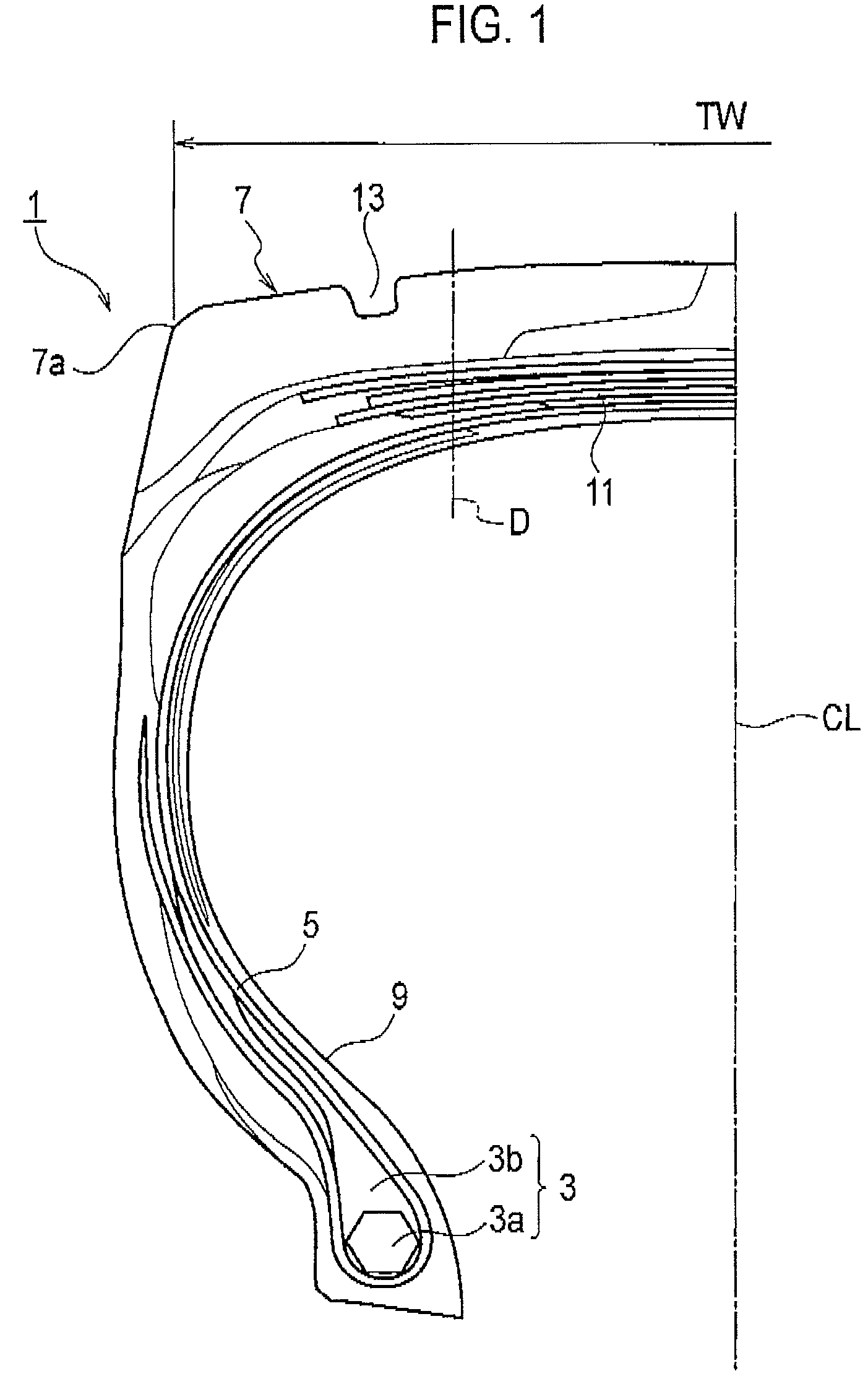
[0043]FIG. 5 is a development view showing a tread pattern of a pneumatic tire according to Modification 3. As shown in FIG. 5, two circumferential-direction main grooves 13 and multiple lug grooves 15 are formed in the tread portion 7. The two circumferential-direction main grooves 13 are disposed outside the respective quarter point sections D of the tread contact width TW (refer to FIG. 1) in the tr...


PUM


Abstract

A pneumatic tire has two circumferential-direction main grooves (13) and lug grooves (15). The circumferential-direction main grooves are disposed outside quarter point sections of a tread contact width (TW) in a tread width direction, respectively, the two circumferential-direction main grooves extending in a tire circumferential direction, each of the quarter point sections of the tread contact width (TW) being a midpoint between a tire equator line and a corresponding tread end portion. The lug grooves are extended outwardly from the circumferential-direction main grooves in the tread width direction. Each quarter point section of the tread contact width (TW) has a rib-like shape continuously extending in the tire circumferential direction.

Description

CROSS REFERENCE TO RELATED APPLICATIONS[0001]This application is a National Stage of International Application No. PCT / JP2008 / 071295 filed Nov. 25, 2008, claiming priority based on Japanese Patent Application No. 2007-318185 filed Dec. 10, 2007, the contents of all of which are incorporated herein by reference in their entirety.TECHNICAL FIELD[0002]The present invention relates to a pneumatic tire, and particularly to a pneumatic tire capable of providing a greatly extended tire lifetime through great improvement in wear resistance.BACKGROUND ART[0003]In the case of a pneumatic tire, called a heavy duty tire, to be mounted on a heavy duty vehicle such as a construction vehicle, conventionally, a tread gauge, which is a thickness of a tread portion, has been increased, or a negative ratio (an area ratio of groove portions to a tread surface) of a tread pattern has been decreased, for the purpose of extending the lifetime before complete wear of a pneumatic tire.[0004]However, the pne...

Claims


Application Information

Patent Timeline
Patent Type & Authority Patents(United States)
IPC IPC(8): B60C11/03
CPCB60C11/04B60C11/0306B60C2200/06B60C2011/0381B60C11/0311B60C2200/065
Inventor AOKI, TOMONORI
Owner BRIDGESTONE CORP
Why Eureka
Try Eureka