Charging rate estimating method, charging rate estimating unit and battery system

a charging rate and charging rate technology, applied in the field of calculating the charge rate of secondary batteries, can solve the problems of difficult to precisely approximate the time characteristics of open circuit voltage, inconvenient charging rate calculation by means of the conventional method, and large errors in the convergent value calculated with the use of the approximate method, so as to achieve more reliable and user-friendly effects

Active Publication Date: 2006-09-21
FURUKAWA ELECTRIC CO LTD
View PDF2 Cites 30 Cited by
  • Summary
  • Abstract
  • Description
  • Claims
  • Application Information

AI Technical Summary

Benefits of technology

[0004] One of the purpose of the present invention is to provide a method for calculating charged rate of a secondary battery which makes it possible to calculate a precise convergent value of the open circuit voltage in a short period of time, and thereby to calculate a precise charged rate.
[0030] As mentioned above, according to the present invention, there is provided the method for calculating charged rate of a secondary battery which calculates the convergent value of the open circuit voltage in a short period of time by approximating the time characteristic of the open circuit voltage of the secondary battery with a quadric or more exponential damping function.

Problems solved by technology

However, it is difficult to precisely approximate the time characteristics of the open circuit voltage with the use of the functions as mentioned above.
As the result, the convergent value calculated with the use of the approximate calculation includes relatively large errors.
Therefore, there is a problem in which the charged rate calculated by means of the conventional method is not precise since the approximate calculation has a limitation to obtain highly preciseness so as to calculate improper charged rate.

Method used


Image

  • Charging rate estimating method, charging rate estimating unit and battery system
  • Charging rate estimating method, charging rate estimating unit and battery system
  • Charging rate estimating method, charging rate estimating unit and battery system

Examples


Embodiment Construction

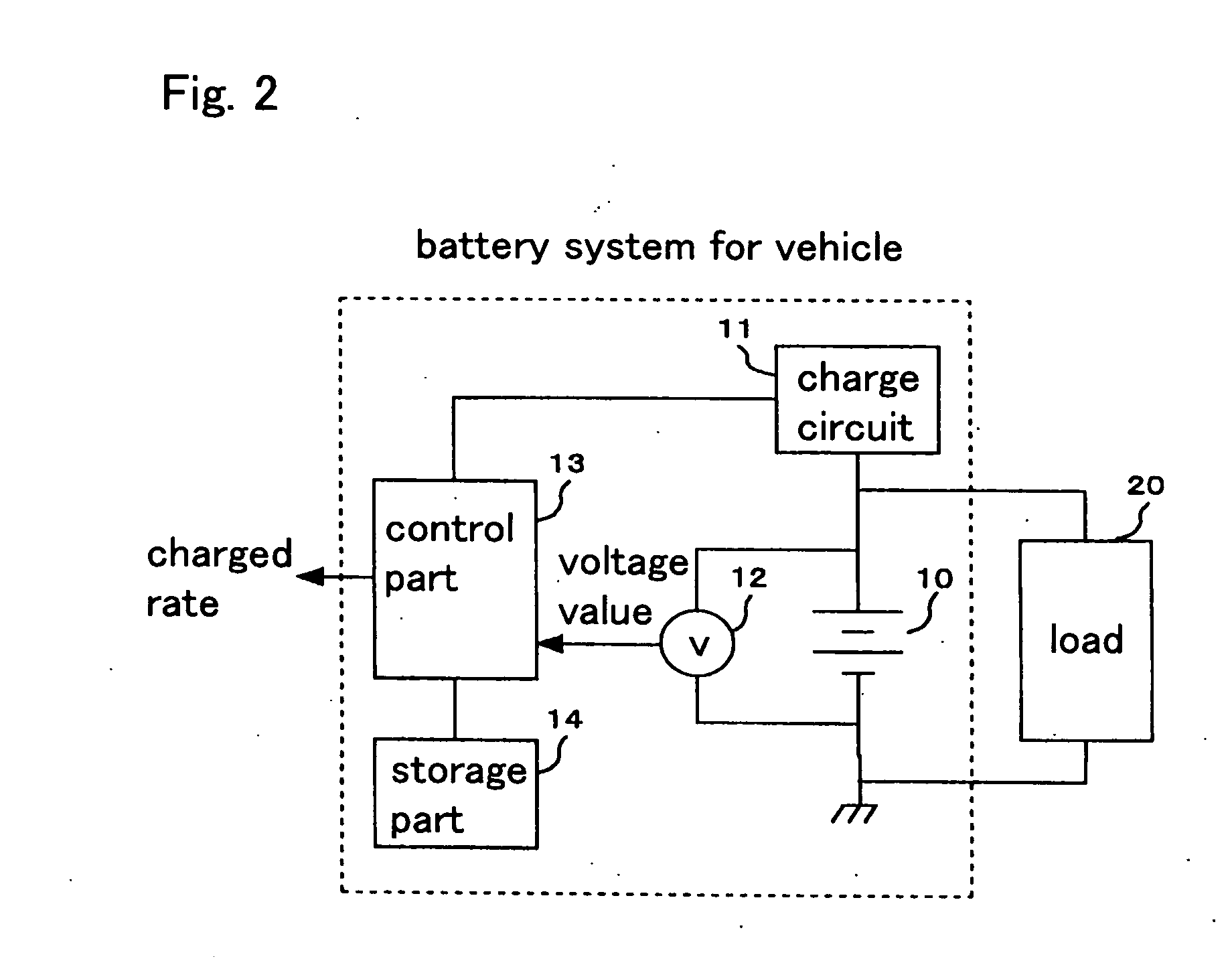
[0045] The preferable embodiments according to the present invention are described below with reference to the drawings. The embodiments are described which are battery systems for vehicle having a function of calculating charged rate of the second battery for backup or power supply of various types of equipments, or second battery for vehicle with secondary battery mounted thereon.

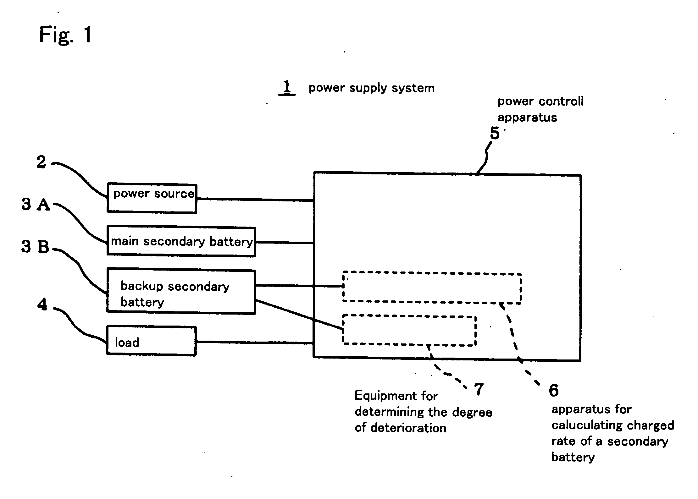
[0046]FIG. 1 is a block diagram showing a schematic construction of a power supply system with secondary battery for power supply of various types of equipments, or for vehicle according to an embodiment. The system shown in FIG. 1 comprises at least two secondary batteries. The secondary battery 3A, one of at least two secondary batteries, is used as a main secondary battery, and the secondary batteries 3B, the other secondary batteries, are used as a backup secondary battery. The charged rate of at least one of the secondary batteries is calculated. For instance, solar battery or power source 2 for veh...


PUM

PropertyMeasurementUnit
standby timeaaaaaaaaaa
voltagesaaaaaaaaaa

Abstract

The method for calculating charged rate of a secondary battery is intended to calculate charged rate of a secondary battery which supplies electric power to loads, and comprises the step to measure voltage of the secondary battery more than once in a predetermined period of time after termination of charge or discharge, the step to determine the coefficients of a quadric or more exponential damping function which approximates the time characteristic of the open circuit voltage of the secondary battery by recursive calculation with the plural measured voltage values, and the step to calculate a convergent value of the open circuit voltage of the secondary battery from at least the exponential damping function with the coefficients determined above. Therefore, precise charged rate of the secondary battery can be calculated from the precise convergent value of the open circuit voltage

Description

FIELD OF THE INVENTION [0001] The present invention relates to a method and apparatus for calculating charged rate of a secondary battery which is employed to supply loads with electric power. BACKGROUND OF THE INVENTION [0002] In a secondary battery for backup or power supply in various types of equipments, or such automotive battery as lead storage battery, it has long been required to exactly determine a remaining electrical charge. In a secondary battery, since the charged rate in general correlates with an open circuit voltage, it is possible to calculate the charged rate from the open circuit voltage. However, it is necessary to measure the open circuit voltage under the condition in which neither charge nor discharge is executed. In addition, it takes long time until the open circuit voltage becomes stable after finishing the charge or discharge. Thus, various methods are proposed for measuring the open circuit voltage in a short time of the secondary battery under the specif...

Claims


Application Information

Patent Timeline
Patent Type & Authority Applications(United States)
IPC IPC(8): H02J7/00B60R16/04G01R31/36H01M10/48
CPCG01R31/3651G01R31/3675G01R31/367G01R31/374
Inventor IWANE, NORIYASUWATANABE, YUICHISUGIMURA, TAKEZOSATOH, TOSHIYUKIKIMURA, ATSUSHIIWAHANA, FUMIKAZUINANIWA, KATSUMIKANOU, TETSUYA
Owner FURUKAWA ELECTRIC CO LTD
Why Eureka
Try Eureka