System and method for global positioning system repeater
a global positioning system and repeater technology, applied in satellite radio beaconing, measurement devices, instruments, etc., can solve the problems of limited gps functionality to outdoor locations, high cost signal processing, and derived altitude measuremen
- Summary
- Abstract
- Description
- Claims
- Application Information
AI Technical Summary
Benefits of technology
Problems solved by technology
Method used
Image
Examples
first embodiment
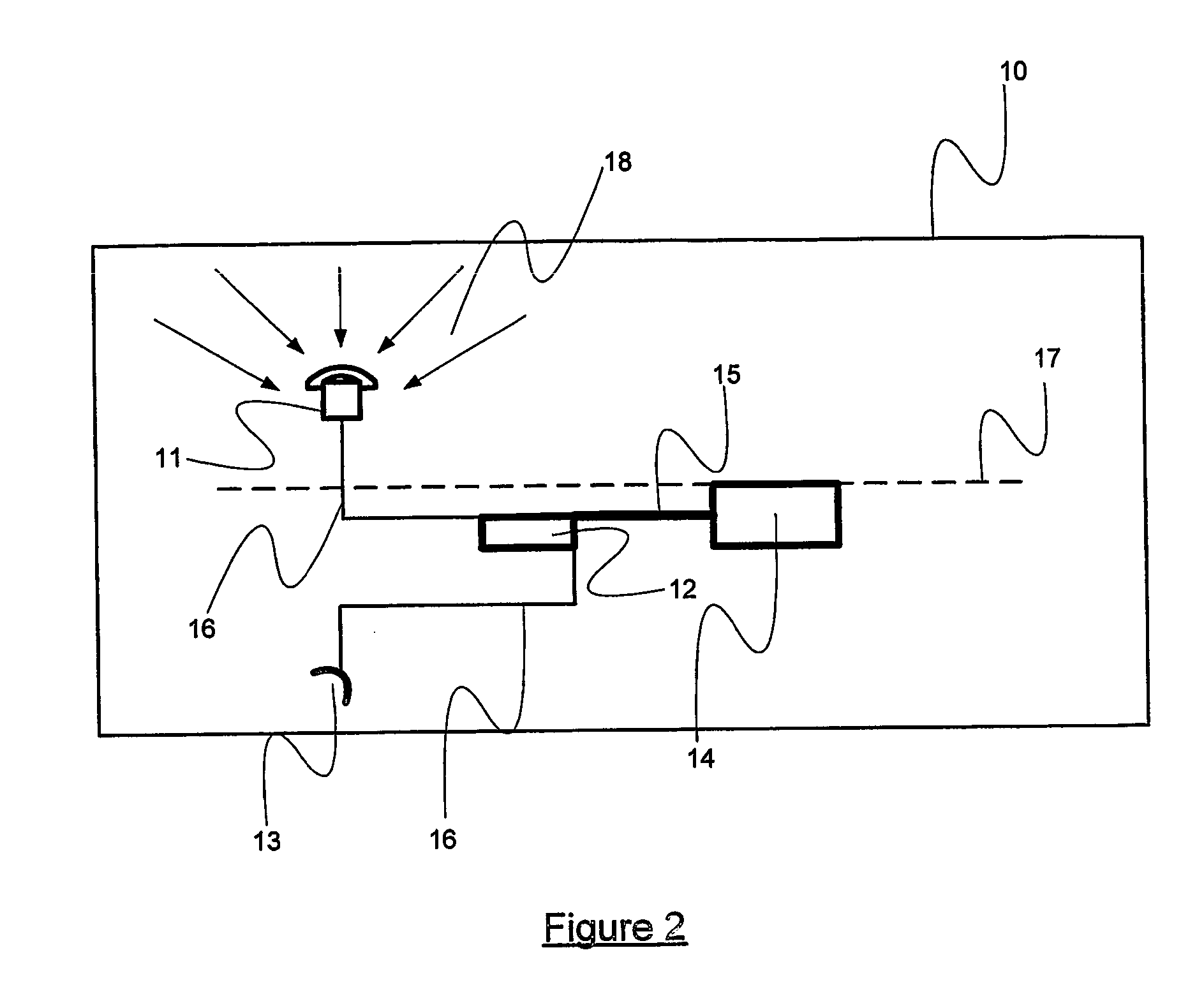
[0047]FIG. 3a shows the directional GPS receive aerial 19 replacing the standard GPS receive aerial 11 as previously shown in FIG. 2. This is the present invention providing innovative location capabilities within a ‘room’.
[0048] By ‘room’ we mean GPS coverage up to at least twenty five meters range from the repeater's indoor radiating aerial such as within a single large room or a parking bay. The result is knowing that a person or object such as, for example a person carrying an Automatic Personal Locater (APL) 21 is within the area.
[0049] The beam width of the repeater's directional receive aerial should be enough to guarantee that any satellite is not received via more than one repeater aerial. As twelve satellites are often visible, and only four are required for a 3-D fix then some gaps in the coverage of the sky is easily tolerated by the system.
[0050] As with all embodiments of the present invention allowances are made for receive aerial gain, radiating element gain, cable...
second embodiment
[0054]FIG. 4a is a block diagram of the present invention providing location capabilities in a defined area such as a larger room, tunnel or corridor. Each repeater 22 is placed at opposite ends of the defined area and cover the entire length having a maximum range of the tunnel length. Typically the maximum length used in this configuration is 50 m.
[0055] This configuration differs from the system shown in FIG. 2 in that it uses directional or screened repeater receive aerials 19a, 19b placed at each end of the test area. Each aerial 19a, 19b is directional so that it only receives GPS signals from a controlled area of the sky. Effectively the system is selecting the satellites to be used. By using different satellites for different repeaters a GPS unit is able to determine where it is in relation to the outer walls of the area. A GPS unit is able to seamlessly proceed from the outside environment into a tunnel or corridor continue through and emerge back into the outside environme...
third embodiment
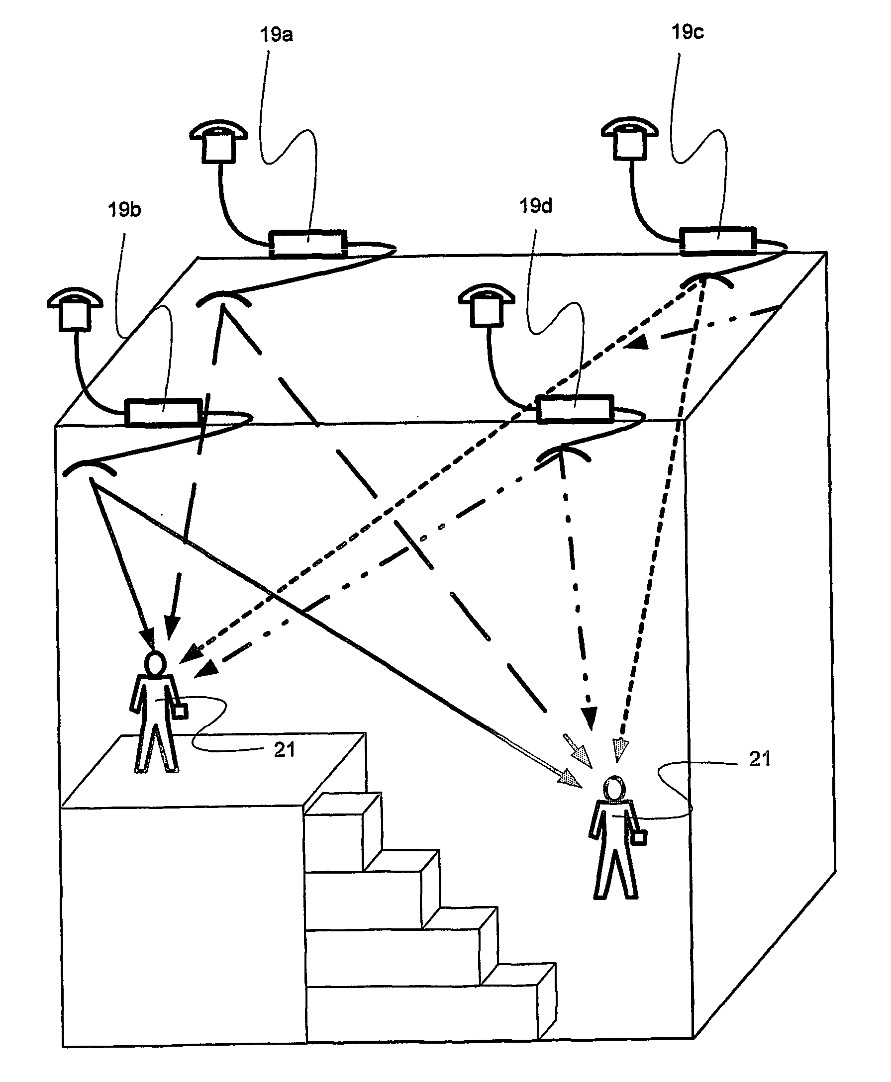
[0057]FIG. 5a is a cross-sectional block diagram of a GPS receiving system 10 of the present invention providing location capabilities in a defined volume such as an indoor space of 75 meters square by 30 m high for example in a shopping mall or in an airport terminal.
[0058] A repeater unit 19a, 19b, 19c, 19d is provided at each corner of the roof area and at each top corner of each successive volume providing three-dimensional location capabilities to determine which part of the volume the GPS unit is in i.e. where it is (latitude and longitude) including floor details. The idea behind this configuration is to establish not only where the person or object is in relation to the outer walls of a building but also what floor or level they are on. Typically having an accuracy of within 5 m horizontally and within a floor (typically 4 m) vertically.
[0059]FIG. 5b is a simplified version of FIG. 5a just showing the position of the repeaters 22.
PUM
 Abstract
Description
Claims
Application Information
 - R&D
- Intellectual Property
- Life Sciences
- Materials
- Tech Scout
- Unparalleled Data Quality
- Higher Quality Content
- 60% Fewer Hallucinations
Browse by: Latest US Patents, China's latest patents, Technical Efficacy Thesaurus, Application Domain, Technology Topic, Popular Technical Reports.
© 2025 PatSnap. All rights reserved.Legal|Privacy policy|Modern Slavery Act Transparency Statement|Sitemap|About US| Contact US: help@patsnap.com


