Apparatus for detecting direction of image pickup device and moving body comprising same

a technology of image pickup and moving body, which is applied in the direction of closed circuit television system, color signal processing circuit, television system, etc., can solve the problem of failure to detect the sun direction

Active Publication Date: 2011-01-27
PANASONIC CORP
View PDF11 Cites 58 Cited by
  • Summary
  • Abstract
  • Description
  • Claims
  • Application Information

AI Technical Summary

Benefits of technology

[0047]According to the present invention, no matter where it is or what posture is taken to carry out shooting on location, the direction of an image capture dev...

Problems solved by technology

In that case, however, if the sunlight reflected on a window is seen at a high position, there will b...

Method used


Image

  • Apparatus for detecting direction of image pickup device and moving body comprising same
  • Apparatus for detecting direction of image pickup device and moving body comprising same
  • Apparatus for detecting direction of image pickup device and moving body comprising same

Examples


embodiment 1

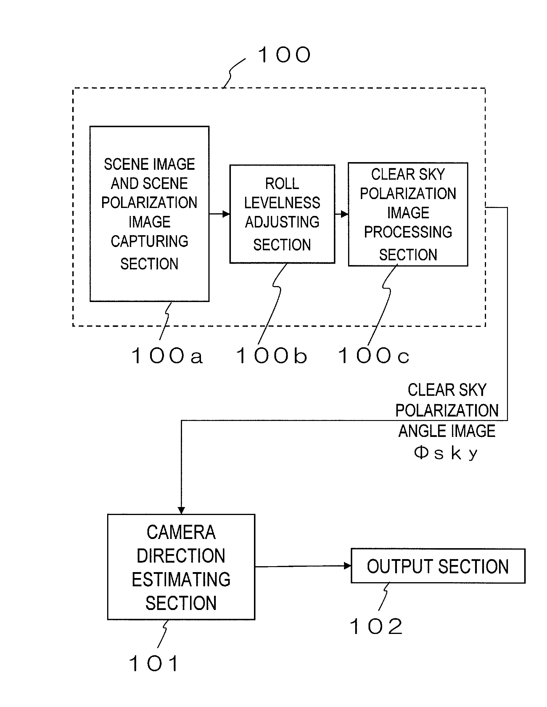
[0118]FIG. 1F Illustrates a configuration of an image capture device as a first specific preferred embodiment of the present invention. This image capture device includes a clear sky polarization angle image capturing section 100, a camera direction estimating section 101, and an output section 102. The clear sky polarization angle image capturing section 100 includes a scene image and scene polarization image capturing section 100a, a roll levelness adjusting section 100b, and a clear sky polarization image processing section 100c and outputs a clear sky polarization angle image φsky.

[0119]As used herein, the “polarization image” refers to an image composed of pixels showing its own polarization information respectively. Also, the “polarization information” includes the degree of polarization and the polarization angle (or direction of polarization). Therefore, unless stated otherwise, the “polarization image” collectively refers to a “degree-of-polarization image” representing the...

embodiment 2

[0248]FIG. 21 is a block diagram illustrating a configuration of a camera direction detector as a second specific preferred embodiment of the present invention. In FIG. 21, any component with substantially the same function as its counterpart shown in FIG. 1F is identified by the same reference numeral and a detailed description thereof will be omitted herein.

[0249]There are a few differences between the first preferred embodiment described above and this preferred embodiment. First of all, although the detector of the first preferred embodiment includes the clear sky polarization angle image capturing section 100 (see FIG. 1F), the detector of this preferred embodiment includes a clear sky polarization image capturing section 1700 (see FIG. 21). As used herein, the “clear sky polarization image” includes both a “clear sky polarization angle image” and a “clear sky degree of polarization image”. That is to say, according to this preferred embodiment, not just the “clear sky polariza...

embodiment 3

[0275]FIG. 28 is a block diagram illustrating a configuration of the direction detector as a third specific preferred embodiment of the present invention. In FIG. 28, any component having substantially the same function as its counterpart shown in FIG. 21 is identified by the same reference numeral and a detailed description thereof will be omitted herein.

[0276]This third preferred embodiment is comprised of the output section 2201, with a part for calculating the sun direction in a camera coordinate system and compiling and outputting, in a predetermined format, data including information about the sun direction and information about the direction of the camera. Hereinafter, the output section 2201 will be described.

[0277]FIG. 29 illustrates a configuration of the output section 2201. A “coordinate transformation section”2301 calculates the sun's position in the camera coordinate system based on the orientation and angle of elevation of the camera. And an “image format generating s...


PUM


Abstract

A polarization camera that can capture polarization images and a color image at the same time is used. Specifically, a clear sky polarization image, which provides information about the polarization of a part of the sky, is captured by a clear sky polarization image capturing section 100. And by reference to the information provided by a sun position determining section 1301 that determines the sun's position at the time of shooting, a camera direction estimating section 101 determines in what direction and in what area of the whole sky the clear sky polarization image is located as a polarization pattern. Finally, information about what direction or orientation on the globe the camera (image capture device) is now facing is output. In this manner, the direction of the camera and the relative position of the camera with respect to the sun can be known without providing a sensor separately and without capturing the whole sky or the sun.

Description

TECHNICAL FIELD[0001]The present invention relates to an apparatus which can detect the direction of the optical axis of the image capture device, with which information about a relative position of an image capture device with respect to the sun can be obtained, and also relates to an image capture device and a vehicle with such a detector.BACKGROUND ART[0002]As digital cameras have become increasingly popular nowadays, the importance of image processing to be performed on images shot with those digital cameras has been increasing year after year. There are various kinds of such image processing, examples of which include (i) compensation for backlight, which has been a major cause of a failure in making a good shot with a camera, (ii) increasing the resolution of a so-called“digitally zoomed” image, (iii) recognizing a human face or something like that and automatically focusing on it, and (iv) superposing a virtual image, generated by computer graphics, on a real image as known a...

Claims


Application Information

Patent Timeline
IPC IPC(8): H04N7/18H04N9/68H04N5/76H04N5/225
CPCH04N5/2628H04N5/2251H04N23/61H04N23/10H04N23/843H04N25/134
Inventor KOMOTO, AYAKOKANAMORI, KATSUHIROSATO
Owner PANASONIC CORP
Why Eureka
Try Eureka